2.7
Date Code 20150130 Instruction Manual SEL-787 Relay
Installation
I/O Configuration
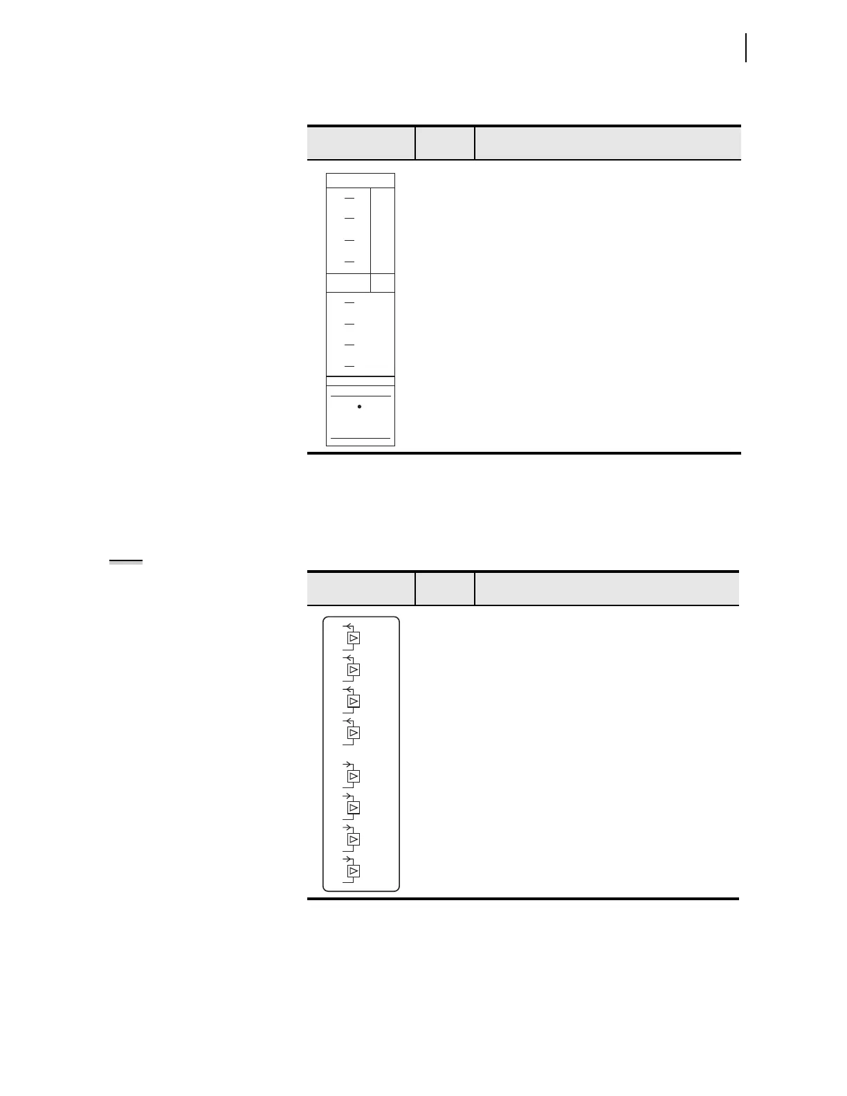
Analog Input/Output
Card (4 AI/4 AO)
Supported in any one of the nonbase unit slots (Slot C, D, or E), this card has
four analog inputs (AI) and four analog outputs (AO). Table 2.6 shows the
terminal allocation.
Table 2.5 1 ACI/3 AVI or 1 ACI Current/Voltage Card Inputs Terminal
Designation
Side-Panel
Connections Label
Term i nal
Number
Description
E01 VA, Phase A voltage input
E02 VB, Phase B voltage input
E03 VC, Phase C voltage input
E04 N, Return for VA, VB, VC
E09, E10 IN1, Neutral current input 1
ACI
AVI
E10
IN
E09
WYE
OPEN
DELTA
E05
E06
N/C
N/C
E08
E07
N/C
N/C
E02 VB
VB
(COM)
E03 VC VC
E04 N COM
VA VAE01
Table 2.6 Four Analog Input/Four Analog Output (4 AI/4 AO) Card Terminal
Allocation
Side-Panel
Connections Label
Term i nal
Number
Description
a
a
x=3, 4, or 5 (for example, AI401, AI402, etc., if the card was installed in Slot D).
01, 02 AOx01, Analog Output number x01
03, 04 AOx02, Analog Output number x02
05, 06 AOx03, Analog Output number x03
07, 08 AOx04, Analog Output number x04
09, 10 AIx01, Transducer Input number x01
11, 12 AIx02, Transducer Input number x02
13, 14 AIx03, Transducer Input number x03
15, 16 AIx04, Transducer Input number x04
NOTE: Analog inputs cannot
provide loop power. Each analog
output is self-powered and has an
isolated power supply.
AO_02
AO_0 1
AO_03
AO_04
AI_02
AI_0 1
AI_03
AI_04
08
05
06
02
04
09
03
10
11
12
13
14
15
16
07
01