2.15
Date Code 20150130 Instruction Manual SEL-787 Relay
Installation
I/O Configuration
Password, Breaker
Control, and SELBOOT
Jumper Selection
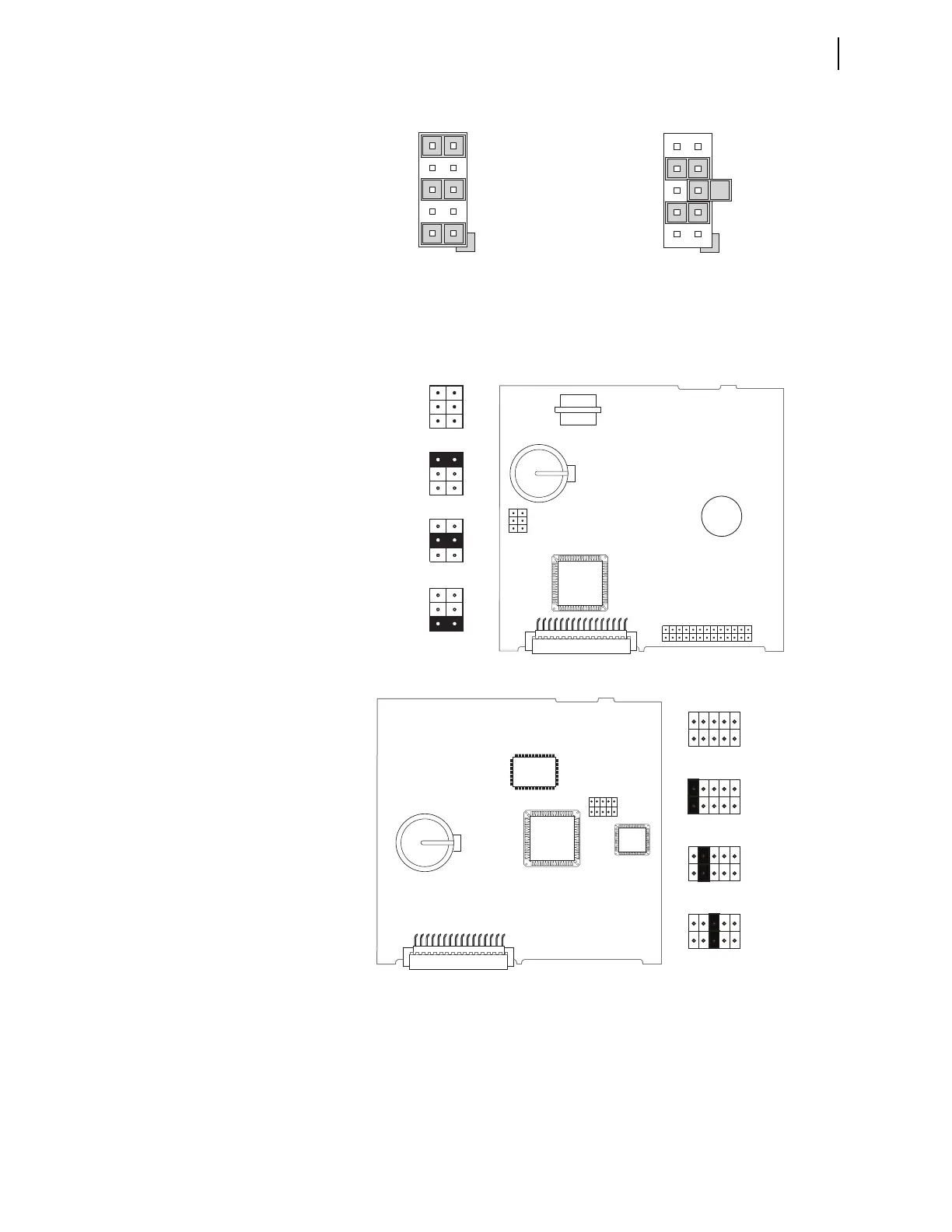
Figure 2.7 shows the major components of the Slot B card in the base unit.
Notice the three sets of pins labeled A, B, and C.
Figure 2.7 Pins for Password Jumper, Breaker Control Jumper,
and SEL
BOOT Jumper
Pins labeled A bypass the password requirement, pins labeled B enable breaker
control, and pins labeled C force the relay to the SEL operating system called
SEL
BOOT. In the unlikely event that the SEL-787 experiences an internal
failure, communication with the relay may be compromised. Forcing the relay
to SEL
BOOT provides you with a way to downloading new firmware. To force
Figure 2.5 Current Output Jumpers Figure 2.6 Voltage Output Jumpers
9
5
1
10
6
2
JMP4
JMP4 Selected as Current Output
7
5
3
8
6
4
JMP1
JMP1 Selected as Voltage Output
JMP1
ABC
JMP1
ABC
JMP1
ABC
JMP1
ABC
Password
Bypassed
Default
Positions
SELBOOT
Forced
Remote
Breaker
Control
Allowed
JMP1
(b) Card Layout for Relays With Firmware Versions R200 and Higher
(a) Card Layout for Relays With Firmware Versions Lower Than R200
A
B
C
JMP1
A
B
C
JMP1
A
B
C
JMP1
Default
Positions
Password
Bypassed
Remote
Breaker
Control
Allowed
A
B
C
JMP1
SELBOOT
Forced
A
B
C
JMP1
A B C