4.33
Date Code 20150130 Instruction Manual SEL-787 Relay
Protection and Logic Functions
Basic Protection
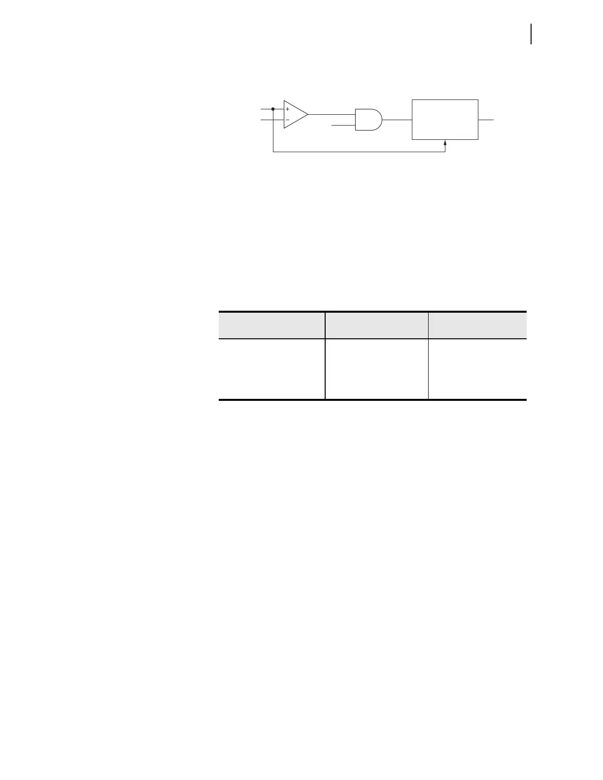
Timing is on an extremely inverse-time overcurrent curve (Curve U4) at the
time-dial setting (0.5) and with 50REF1P as the pickup setting.
Figure 4.16 REF Protection Output (Extremely Inverse-Time O/C)
Relay Word bit REF1F (forward fault) torque controls the timing curve, and
IN1PU operates the timing function. The curve resets in one cycle if current
drops below pickup or if REF1F deasserts. When the curve times out, Relay
Word bit REF1P asserts. You can use this bit directly as an input to the
appropriate trip variables, TRx (where x = 1 or XFMR), to trip the breaker or
breakers that feed the fault.
Setting Descriptions and Applications
Table 4.6 identifies the settings associated with the REF1 element.
The setting REF1POL tells the relay which winding or combination of
windings it should use in calculating residual current, which acts as the
polarizing quantity for the corresponding directional element, Figure 4.13.
The setting REF1TC is a SEL
OGIC control equation setting that defines the
conditions under which the relay enables the corresponding REF1 element.
You can set the neutral current sensitivity threshold, 50REF1P, to as low as
0.05 times nominal current for a 1 A CT (0.25 A for 5 A nominal CT current),
the minimum neutral current sensitivity of the relay. However, the minimum
acceptable value of 50REF1P must be greater than any natural 3I0 unbalance
resulting from load conditions.
Selection of the Restraint Quantity
The operating quantity/polarizing quantity relationship is according to
software assignment (instead of a fixed relationship), so you can apply the
REF element to any primary plant configuration with the correct CT
arrangement. In general, identify all lines that are electrically connected to the
grounded winding that you want to protect with the REF element. Then enter
those terminals at the REF1POL setting. Following are examples of a few
applications, assuming that both differential and REF elements protect the
transformer in each example.
Figure 4.17 shows an ungrounded HV winding and a grounded-wye LV
winding. Because two terminals are needed for the differential protection,
assign Terminal 1 to the HV side and Terminal 2 to the LV side. Configure the
REF1 element for REF protection. This element requires that the neutral CT is
wired to Terminal IN. Although Terminals 1 and 2 are enabled, only Terminal
|INWPU1|
50REF1P
C1
REF1F
AND
REF1PP
50REF1P (Pickup)
U4 Curve
TD 0.5
Reset 1 Cycle
REF1P
Table 4.6 Restricted Earth Fault Settings
Setting Prompt Setting Range
Setting Name :=
Fac tory Defau lt
POL QTY FROM WDG OFF, 1, 2, 12 REF1POL := OFF
REF1 TRQ CTRL SEL
OGIC REF1TC := 1
REF1 CURR LEVEL 0.05–3.00 pu 50REF1P := 0.25
52A BYPASS ENABL Y, N REF52BYP := Y