4.32
SEL-787 Relay Instruction Manual Date Code 20150130
Protection and Logic Functions
Basic Protection
torque quantity REFTQ1 (this calculation is equivalent to |IOP1| times
|IPOL1| times the cosine of the angle between them). REFTQ1 is positive if
the angle is within ±90 degrees, indicating a forward or internal fault.
Conversely, REFTQ1 is negative if the angle is greater than +90 or less than
–90 degrees, indicating a reverse or external fault.
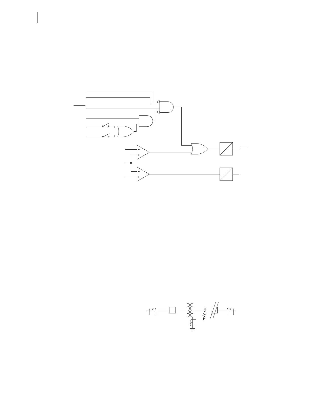
Figure 4.14 shows the logic that compares REFTQ1 to positive threshold
(THRES1P) and negative threshold (THRES1N), to ensure security for very
small currents or for an angle near +90 or –90 degrees.
Figure 4.14 REF Element Trip Output
If REFTQ1 exceeds either threshold, it must persist for at least 1.5 cycles
before Relay Word bit REFF1 (forward) or REFR1 (reverse) asserts. Assertion
of REFF1 constitutes an internal ground fault.
A second path can also assert the REF1F bit. This path comes from the output
of the AND gate in Figure 4.14, REF1 bypass logic. Assertion of this gate
indicates substantial neutral current and no line-end current flow. Figure 4.15
shows the need for the bypass logic. For the directional element to produce a
meaningful result, both operating and restraint quantities must be present. If
Fault F1 occurs with the LV breaker open, no current flows through the LV
CT, and there is no polarizing quantity present. Assertions of 50NREF1 and a
negated 50GREF1 identify this condition in Figure 4.14. Under this condition,
the output of the bypass logic, REF1BYP, causes the REF1F bit to assert to
clear the internal fault. In most applications with REF52BYP:=Y, a 52A
interlock enhances performance of the logic. Set REF52BYP := 0 if your
application requires disregarding 52A for the bypass (e.g., the protected
transformer is the only source of zero-sequence fault current).
Figure 4.15 Internal Fault With LV Breaker Open
For fast tripping, include REFF1, the output of the REF1 element, into one or
more of the trip equations, TRx (where x = 1, 2, or XFMR) as appropriate. If
you want additional security, the relay is programmed to use REF1F to torque
control an inverse-time curve for delayed tripping, as discussed in the
following text. Figure 4.16 shows the output of the REF1 protection function.
THRES1P
REFTQ1
THRES1N
1.5 cyc
0.0 cyc
1.5 cyc
0.0 cyc
C1
C2
REF1BY
OR
REF1FP
REF1RP
REF1F
REF1R
Relay
Word
Bits
50GREF1
50NREF1
Settings
REF1TC
REF52BYP := Y
52A1
52A2
REF1POL := 1, 12
REP1POL := 2, 12
52 52
F1
Terminal 2
HV
LV Terminal 1



 To Next Page