4.40
SEL-787 Relay Instruction Manual Date Code 20150130
Protection and Logic Functions
Basic Protection
The residual time-overcurrent elements, 51G1T and 51G2T, respond to
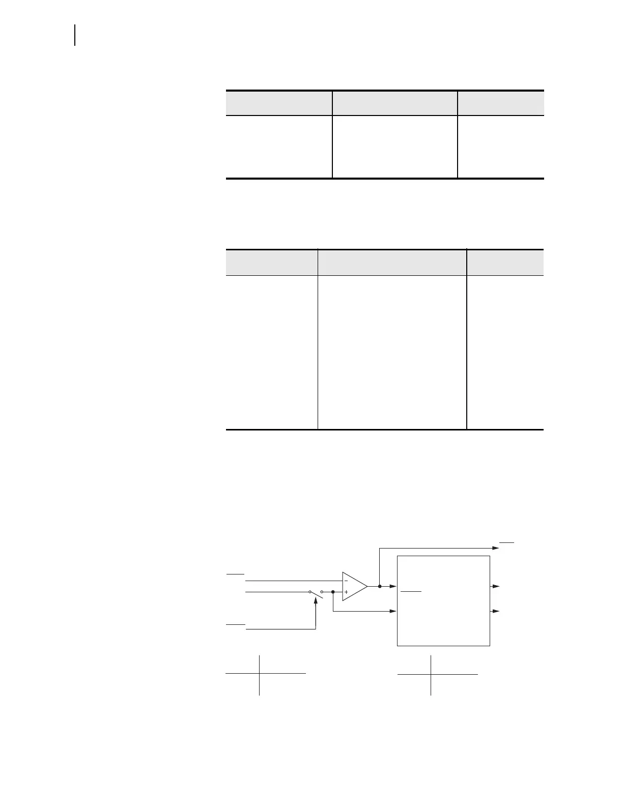
residual currents IGW1 and IGW2 as shown in Figure 4.22.
Figure 4.22 Residual Time-Overcurrent Elements 51G1T and 51G2T
EM RESET DELAY Y, N 51PnCRS := N
CONST TIME ADDER 0.00–1.00 sec 51PnCCT := 0.00
MIN RESPONSE TIM 0.00–1.00 sec 51PnCMR := 0.00
PH A TOC TRQCTRL SEL
OGIC 51PnCTC := 1
a
For I
NOM
=5 A.
b
For I
NOM
=1 A.
c
For 51_C := U_.
d
For 51_C := C_.
Table 4.12 Residual Time-Overcurrent Settings (n = 1 or 2)
Setting Prompt Setting Range
Setting Name :=
Fac tory Defau lt
RES TOC LEVEL OFF, 0.50–16.00 A
a
,
0.10–3.20 A
b
a
For I
NOM
=5 A.
b
For I
NOM
=1 A.
51GnP := OFF
51GnP := OFF
RES TOC CURVE U1, U2, U3, U4, U5,
C1, C2, C3, C4, C5
51GnC := U3
RES TOC TDIAL 0.50–15.00
c
,
0.05–1.00
d
c
For 51_C := U_.
d
For 51_C := C_.
51GnTD := 1.50
EM RESET DELAY Y, N 51GnRS := N
CONST TIME ADDER 0.00–1.00 sec 51GnCT := 0.00
MIN RESPONSE TIM 0.00–1.00 sec 51GnMR := 0.00
RES TOC TRQCTRL SEL
OGIC 51GnTC := 1
Table 4.11 Winding n Phase A, B, and C Time-Overcurrent (n = 1 or 2)
(Sheet 2 of 2)
Setting Prompt Setting Range
Setting Name :=
Fac tory Defau lt
51GnP
|IGWn|
Setting
51GnTC
Torque Control Switch
SEL
OGIC
Torque Control
Pickup
Curve
Timeout
Reset
51GnP
51GnR
51GnT
51GnTC Torque Control
State Switch Position
Logical 1 Closed
Logical 0 Open
Setting
51GnRS = Reset Timing
Y Electromechanical
N 1 Cycle
Relay
Word
Bits
SELOGIC
Setting
(From Figure 4.14)
Note: 51G1T element shown above; 51G2T is similar.
51G1T Residual
Time-Overcurrent Element
Curve Timing and Reset Timing
51GnP Pickup
51GnC Curve Type
51GnTD Time Dial
51GnRS Electromechanical
Reset? (Y/N)
51GnCT Const. Time Add.
51GnMR Min. Response
Settings
 Loading...


