2.21
Date Code 20150130 Instruction Manual SEL-787 Relay
Installation
Rear-Panel Connections
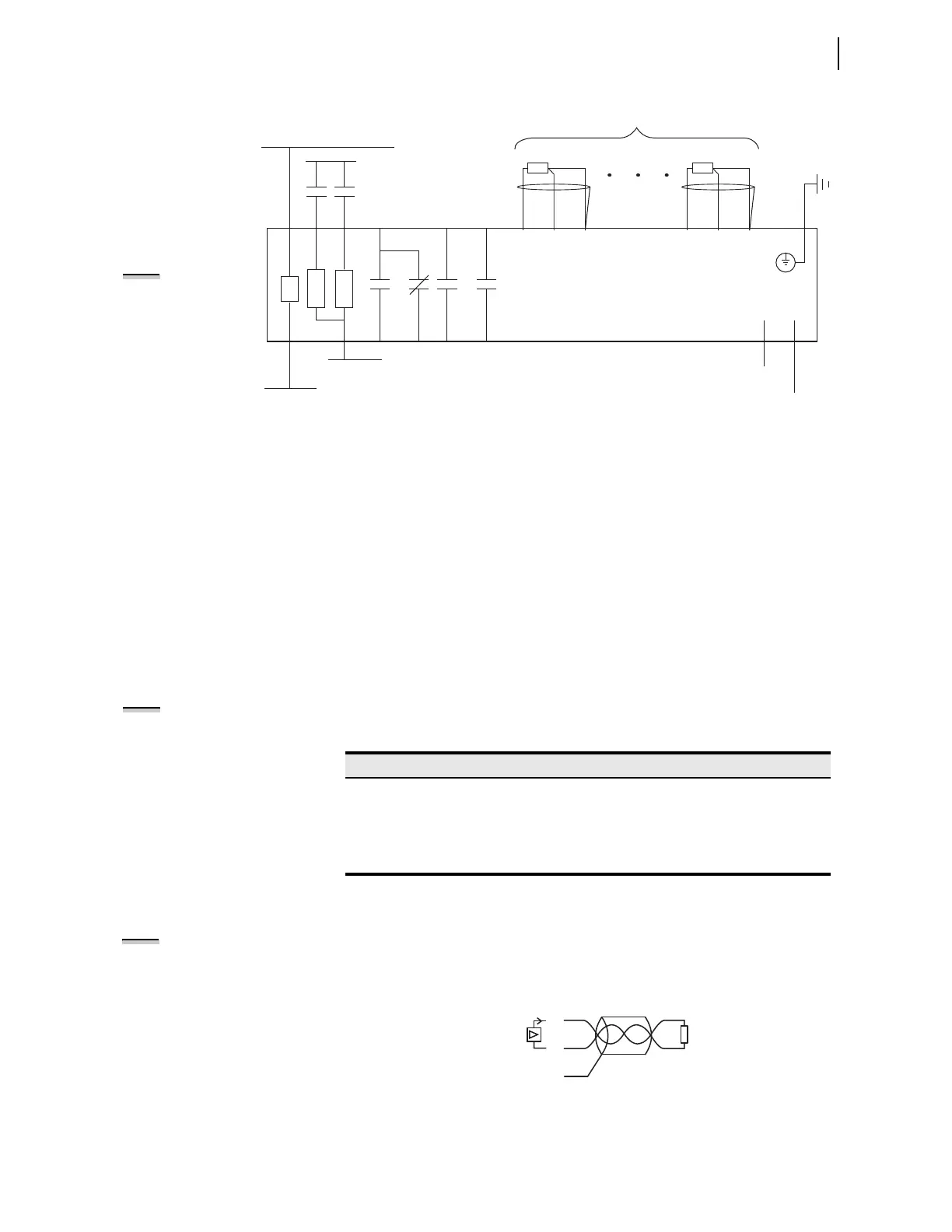
Figure 2.13 Control I/O Connections—Internal RTD Option
Table 2.13 shows the maximum cable lengths for the RTD connections.
Analog Output Wiring
Connect the two terminals of the analog output as shown in Figure 2.14. Also
connect the analog output cable shield to ground at the relay chassis ground,
programmable logic controller (PLC), or meter location. Do not connect the
shield to ground at both locations.
Figure 2.14 Analog Output Wiring Example
PS
A01
A02
–/N
+/H
External
Contacts
SEL-787 Relay
IN101
IN102
A10
A11
A12
+IRIG-B
–IRIG-B
IRIG-B
B01 B02
A07
A08
OUT103
A03
A04
OUT101
A05
A06
OUT102
A09
D03
COMP/
SHLD
D02
—
D01
+
RTD01
D30
COMP/
SHLD
D29
—
D28
+
RTD10
As Many as Ten RTD Inputs
Notes:
• The chassis ground connector located on the rear-panel card Slot A must always be connected to the
local ground mat.
• Power supply rating (125–250 Vac/dc or 24–48 Vdc) depends on relay part number.
• Optoisolated inputs IN101 and IN102 are standard and located on the card in Slot A.
• All optoisolated inputs are single-rated: 24, 48, 110, 125, 220, or 250 Vac/Vdc. Standard inputs IN101/102
may have a different rating than the optional IN401/402/403/404 (not shown).
• Output contacts OUT101, OUT102, and OUT103 are standard and located on the card in Slot A.
• The Analog (transducer) Outputs shown are located on the optional I/O Expansion card in Slot D.
• The fiber-optic serial port is located on the card in Slot B. A Simplex 62.5/125 µm fiber-optic cable is
required to connect the SEL-787 with an SEL-2600 series RTD Module. This fiber-optic cable should be
1000 meters or shorter.
NOTE: All RTD
Comp/Shield
terminals are
internally
connected to the
relay chassis and
ground.
Table 2.13 Typical Maximum RTD Lead Length
RTD Lead AWG Maximum Length (meters)
24 290 m
22 455 m
20 730 m
18 1155 m
NOTE: RTD inputs are not internally
protected for electrical surges
(IEC 60255-22-1 and IEC 60255-22-5).
External protection is recommended
if surge protection is desired.
NOTE: Connection of dc voltage to
the analog output terminals could
result in damage to the relay.
Analog Output
Relay Chassis Ground
Meter
or
PLC
AO_0 1
02
01