2.20
SEL-787 Relay Instruction Manual Date Code 20150130
Installation
Rear-Panel Connections
ST fiber-optic port. The SEL-2800 family of transceivers provides fiber-optic
links between devices for electrical isolation and long-distance signal
transmission. Contact SEL for further information on these products.
IRIG-B Time-Code Input
The SEL-787 accepts a demodulated IRIG-B time signal to synchronize the
internal clock with an external source. SEL-787 relays with an EIA-485 serial
port option for Port 3 have an external IRIG-B input at terminals B01 and B02.
SEL-787 relays with an EIA-232 serial port option for Port 3 have the IRIG-B
available in the EIA-232 port and can be connected to an SEL
communications processor. The available communications processors are the
SEL-2032, SEL-2030, SEL-2020, and the SEL-2100 Logic Processor.
Ethernet Port
The SEL-787 can be ordered with optional single/dual communications ports
of a 10/100BASE-T or 100BASE-FX Ethernet port. Connect to Port 1 of the
device using a standard RJ45 connector for the copper port and an LC
connector for the fiber-optic port.
Fiber-Optic Serial Port
The optional fiber-optic serial port is compatible with the SEL-2812 Fiber-
Optic Transceiver and SEL-2600 RTD Modules.
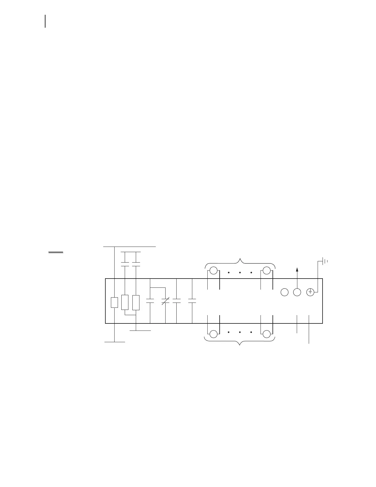
I/O Diagram
A more functional representation of two of the control (I/O) connections are
shown in Figure 2.12 and Figure 2.13.
Figure 2.12 Control I/O Connections—4 AI/4 AO Option in Slot D and Fiber-Optic Port in Slot B
Fiber-Optic Cable
to SEL-2600 series
+IRIG-B
–IRIG-B
IRIG-B
PS
A01
A02
–/N
+/H
External
Contacts
SEL-787 Relay
RX
D07
+
As Many as Four Analog Outputs
D08
—
B01 B02
IN101
IN102
A10
A11
A12 A07
A08
OUT103
+
D15
—
D16
D02
—
—
D10
D01
+
+
D09
A03
A04
OUT101
A05
A06
OUT102
A09
TX
As Many as Four Analog Inputs
AO401 AO404
AI401 AI404
++
++
NOTE: All digital input
and digital output
(including high-current ,
high-speed hybrid)
connections are polarity
neutral.