LTR
DESCRIPTION
CONFIGURATION BASELINE
DATE
APPD
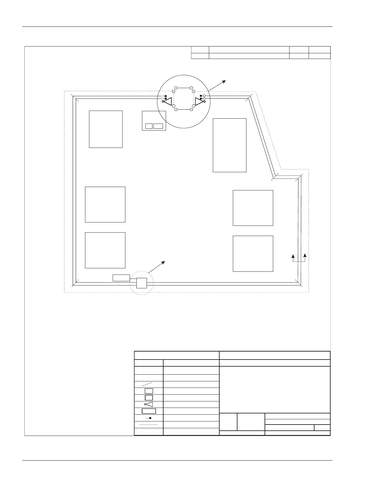
See View 'A'
Zone 2
Zone 9
MW Zone 1
Security
Control
Administration
Health Care/
Education
Center
Zone 3
Zone 4
Living Unit 4
Living Unit 3
Zone 5
Living Unit 1
Living Unit 2
Zone 8
See View 'B'
Zone 6
Zone 7
NOTE:
1. Fences are 8 m apart; cables are buried 1.5 m apart
(inside perimeter fence not shown).
2. Refer to site survey for distance measurements.
3. See table on Page 3 for Processor configurations.
4. Zone layout sequential clockwise.
5. Relay output alarm communication cable and
EIA-422 data cables bundled along fence top between
processor and NIU.
LEGEND
SYMBOL
MEANING
OmniTrax PROCESSOR
ALARM ZONE LABEL
ALARM ZONE BOUNDARY
NETWORK INTERFACE UNIT
NM & UCM COMPUTER
UltraWave MICROWAVE
POWER SUPPLY
TERMINATOR
OUTSIDE PERIMETER FENCE
Sample OmniTrax OC2 Site Plan
1 Standalone processor, 1 Microwave
(Relay Output Alarm Communications
NM & UCM Computer for Remote
Maintenance and Diagnostic Activity)
SIZE
FSCM No.
PART NUMBER
DRAWING NUMBER
VAR.
3
OF
1
SHEET
SCALE
Zone #
PROCESSOR CABLE ID
B
Section
A-A
P1
P1
NIU
PC
12 V
P1-A
P1-A
P1-B
12 V
PC
NIU