LTR
DESCRIPTION
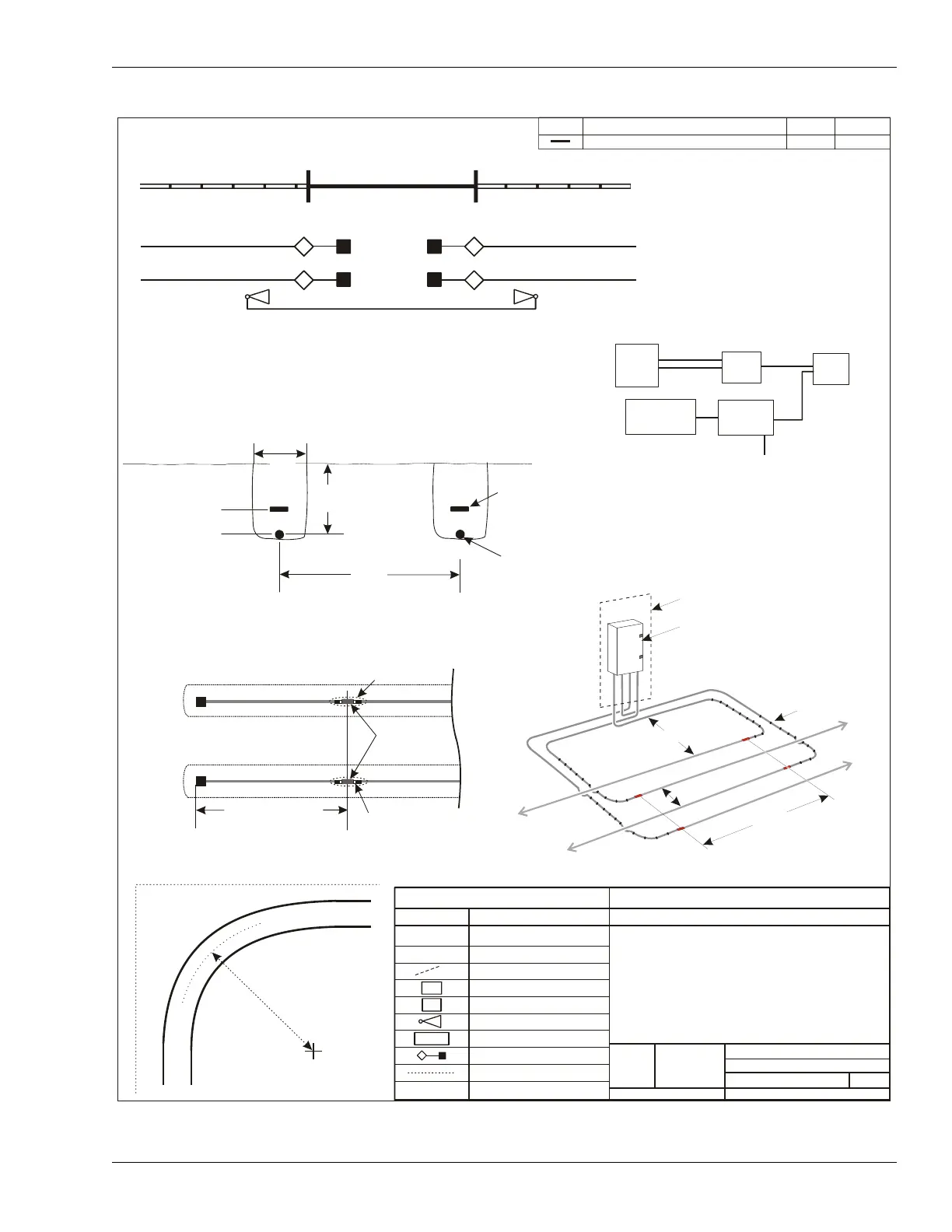
CONFIGURATION BASELINE
DATE
APPD
VIEW 'A'
gate fence
long
terminators
P1-A sensor cables
P1-B sensor cables
ALARM REPORTING DETAIL
USB
cables
NM &
UCM
PC
NIU
relay
interface
alarm
annunciator
UltraWave
microwave receiver
relay output alarm
data cables
EIA-422
cables
P-1
SECTION A-A
10 cm (4 in.)
minimum
ground Level
23 cm
(9 in.)
marker Tape
sensor Cable
1.5 m
(4 ft., 11 in.)
air
soil
7.5 cm (3 in.)
TERMINATOR DETAIL
heatshrink
standalone
decouplers
NOT TO SCALE
distances are approximate
min. 4 m (13 ft.)
terminator.
male TNC connector
VIEW 'B’
telecom enclosure
processor enclosure
NOT TO SCALE
ferrite beads
Zone 7
Zone 6
2.5 m (8 ft.)
8 m (26 ft.)
overlap
3
0
c
m
(
1
2
i
n
.
)
LEGEND
SYMBOL
MEANING
OmniTrax PROCESSOR
ALARM ZONE LABEL
ALARM ZONE BOUNDARY
NETWORK INTERFACE UNIT
UCM/NM COMPUTER
UltraWave MICROWAVE
POWER SUPPLY
TERMINATOR
OUTSIDE PERIMETER FENCE
PROCESSOR CABLE ID
SIZE
FSCM No.
PART NUMBER
DRAWING NUMBER
VAR.
3
OF
2
SHEET
SCALE
Sample OmniTrax OC2 Site Plan
1 Standalone processor, 1 Microwave
(Relay Output Alarm Communications
UCM Computer for Remote Maintenance
and Diagnostic Activity)
Zone #
CORNER DETAIL
7 m (23 ft.)
turn radius
UltraWave microwave sensor
P-1
NIU
PC
12VDC
P1-B
B