LTR
DESCRIPTION
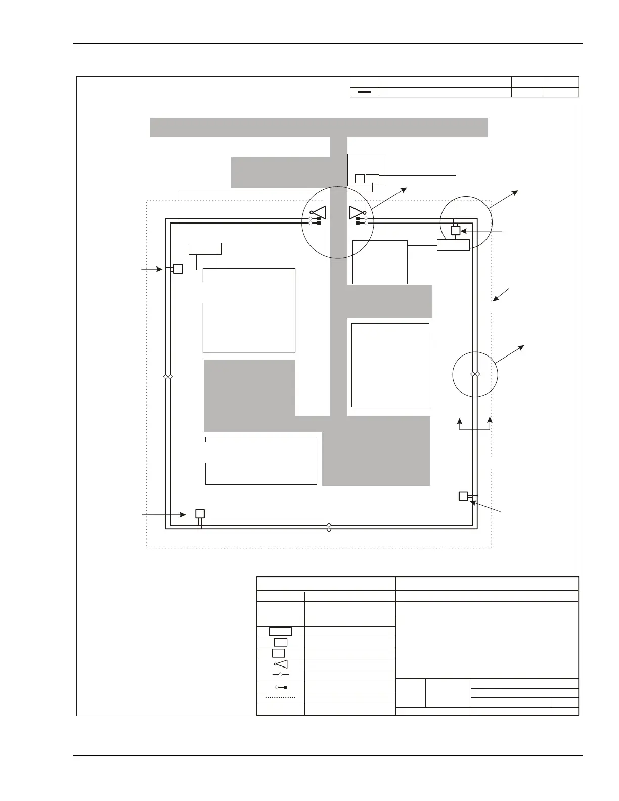
CONFIGURATION BASELINE
DATE
APPD
Main St.
Visitor Parking
EIA-422
North
EIA-422
Security
Control
Administration
Processor #1
F4 in, F3 out
distributes power
over TX cable
Processor #4
F3 in, F4 out
distributes power
over RX cable
Z36 - Z39
Z31 - Z35
Z1 - Z4
Z5 - Z9
Building #1
Building #2
Parking
Parking
Z26 - Z30
Z10 - Z15
P1-A
See View 'C'
Processor #2
F3 & F4 out
Processor #3
F3 & F4 out
Z21 - Z25
Z16 - Z20
External Perimeter
Fence
LEGEND
SYMBOL
MEANING
OmniTrax PROCESSOR
SECURITY LIGHTING
NETWORK POWER SUPPLY
NETWORK INTERFACE UNIT
UCM & NM COMPUTER
UltraWave MICROWAVE
DECOUPLER
TERMINATOR
OUTSIDE PERIMETER FENCE
PROCESSOR CABLE ID
SIZE
FSCM No.
PART NUMBER
DRAWING NUMBER
VAR.
51
SHEET
SCALE
Sample OmniTrax OC2 Site Plan
(4 Processors, 1 Microwave)
OF
Processor #
NOTE:
1. Fences are 7.5 m apart; cables are buried 1.5 m apart
(inside fence not shown).
2. Refer to site survey for distance measurements.
3. See table on Page 4 for Processor configurations.
4. Zone layout sequential clockwise.
Shipping
See View 'A'
See View 'B'
SL10 - SL15
SL16 - SL20
SL21 - SL25
SL26 - SL30
SL31 - SL35
SL36 - SL39
SL1 - SL4
SL5 - SL9
PC
NIU
48VDC
48VDC