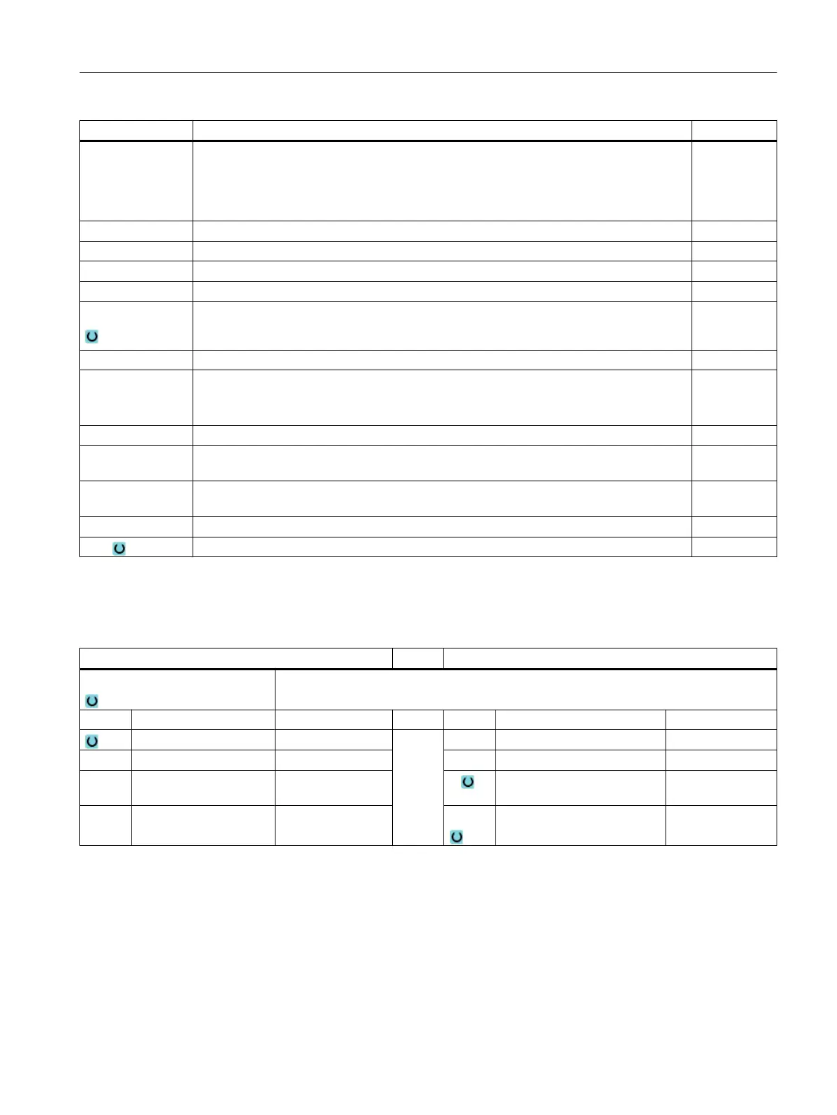
Parameter Description Unit
X0
Y0
Z0
The positions refer to the reference point:
Reference point X – (for single position only)
Reference point Y – (for single position only)
Reference point Z – (single position only and G Code position pattern)
mm
mm
mm
W Width of spigot mm
L Length of spigot mm
R Corner radius mm
α0 Angle of rotation Degrees
Z1 Spigot depth (abs) or depth relative to Z0 (inc) - (only for ∇ and ∇∇∇) mm
DZ Maximum depth infeed - (only for ∇ and ∇∇∇) mm
UXY Plane finishing allowance for the length (L) and width (W) of the rectangular spigot.
Smaller rectangular spigot dimensions are obtained by calling the cycle again and pro‐
gramming it with a lower finishing allowance. - (only for ∇ and ∇∇∇)
mm
UZ Depth finishing allowance (tool axis) - (only for ∇ and ∇∇∇) mm
W1 Width of blank spigot (important for determining approach position) - (only for ∇ and
∇∇∇)
mm
L1 Length of blank spigot (important for determining approach position) - (only for ∇ and
∇∇∇)
mm
FS Chamfer width for chamfering - (for chamfering only) mm
ZFS Insertion depth of tool tip (abs or inc) - (for chamfering only) mm
* Unit of feedrate as programmed before the cycle call
Parameters in the "Input simple" mode
G code program parameters ShopMill program parameters
Input
● simple
Milling direction T Tool name
RP Retraction plane mm D Cutting edge number
F Feedrate * F Feedrate mm/min
mm/rev
S / V Spindle speed or constant
cutting rate
rpm
m/min
Programming technological functions (cycles)
10.2 Milling
Milling
Operating Manual, 08/2018, 6FC5398-7CP41-0BA0 439
 Loading...


