XTRA Operator’s Manual 20077/021 US
List of Figures
Chapter 1: Introduction and Safety
Chapter 2: Overview
Figure 2-1 Position of Separated Whole Blood Components in Centrifuge Bowl ........................................................2-3
Chapter 3: System Description
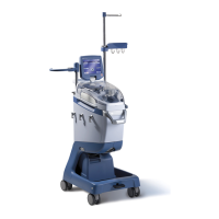
Figure 3-1 XTRA Front View .................................................................................................................................3-1
Figure 3-2 X
TRA Rear View ...................................................................................................................................3-2
Figure 3-3 Front Handle (left), Rear Handle (center), and Rear Transport Handle (right) .........................................3-3
Figure 3-4 Hooks on Left Side of X
TRA .................................................................................................................3-3
Figure 3-5 Left: Disposable Tray on Tray Holders; Right: Waste Bag on Right-Side Hooks .......................................3-4
Figure 3-6 Cart ..................................................................................................................................................3-4
Figure 3-7 Spring Lever Releases Cart ..................................................................................................................3-5
Figure 3-8 Lifting Body from Cart .........................................................................................................................3-5
Figure 3-9 X
TRA Body and Cart .............................................................................................................................3-6
Figure 3-10 Reservoir and IV Pole .........................................................................................................................3-6
Figure 3-11 Reservoir Holder .................................................................................................................................3-7
Figure 3-12 X
TRA Touch Screen Display Panel ........................................................................................................3-8
Figure 3-13 Centrifuge Assembly ...........................................................................................................................3-9
Figure 3-14 Centrifuge Well Fluid Container ......................................................................................................... 3-10
Figure 3-15 Left: Clamps With Clamp Lid Open | Right: Clamp Lid Closed and Latched .......................................... 3-11
Figure 3-16 Visible Parts of the X
TRA Processing Pump ........................................................................................... 3-12
Figure 3-17 Location of the Air Detector ............................................................................................................... 3-12
Figure 3-18 Location of the Hematocrit and Waste Line Color Indicators ................................................................. 3-13
Figure 3-19 Left: Vacuum Module | Right: Integrated Vacuum Module ................................................................ 3-13
Figure 3-20 X
VAC Release Screw ........................................................................................................................... 3-14
Figure 3-21 X
VAC Control Panel ............................................................................................................................ 3-14
Figure 3-22 X
TRA With Disposable Set Installed (Front View) ................................................................................. 3-15
Figure 3-23 X
TRA With Disposable Set Installed (Top View) .................................................................................... 3-16
Figure 3-24 X
TRA Collection Kit (CARDIO TOP) ...................................................................................................... 3-17
Figure 3-25 X
TRA Collection Reservoir (TOP version) ............................................................................................. 3-18
Figure 3-26 Collection Reservoir Lid Ports ............................................................................................................ 3-18
Figure 3-27 Left: Reservoir with TOP Outlet | Right: Reservoir with BOTTOM Outlet .............................................. 3-19
Figure 3-28 Aspiration Line .................................................................................................................................. 3-20