Objet30 User Guide 6 Operating and Maintaining the Printer
DOC-34025 Rev. I 6-49
❒ The top row was printed by the head used for applying Model material
when producing models. From right to left, the columns represent heads
M1, M2, M3, respectively. (There is no column for head M0 because its
alignment is used as a reference for aligning all other heads.)
❒ The bottom row was printed by the head used for applying Support
material.
9. Use a magnifying glass or loupe to inspect the transparency.
Optimum head alignment is shown when the two #8 lines, in the upper and
lower rows, are aligned, Figure 6-63. In the example shown, no change to
the head alignment is necessary. If other lines in the set are aligned, you
need to change the alignment—in the next wizard screen.
10. In the wizard screen shown in Figure 6-62, select the Transparency
removed check box, and click Next.
The first in a series of alignment screens appears.
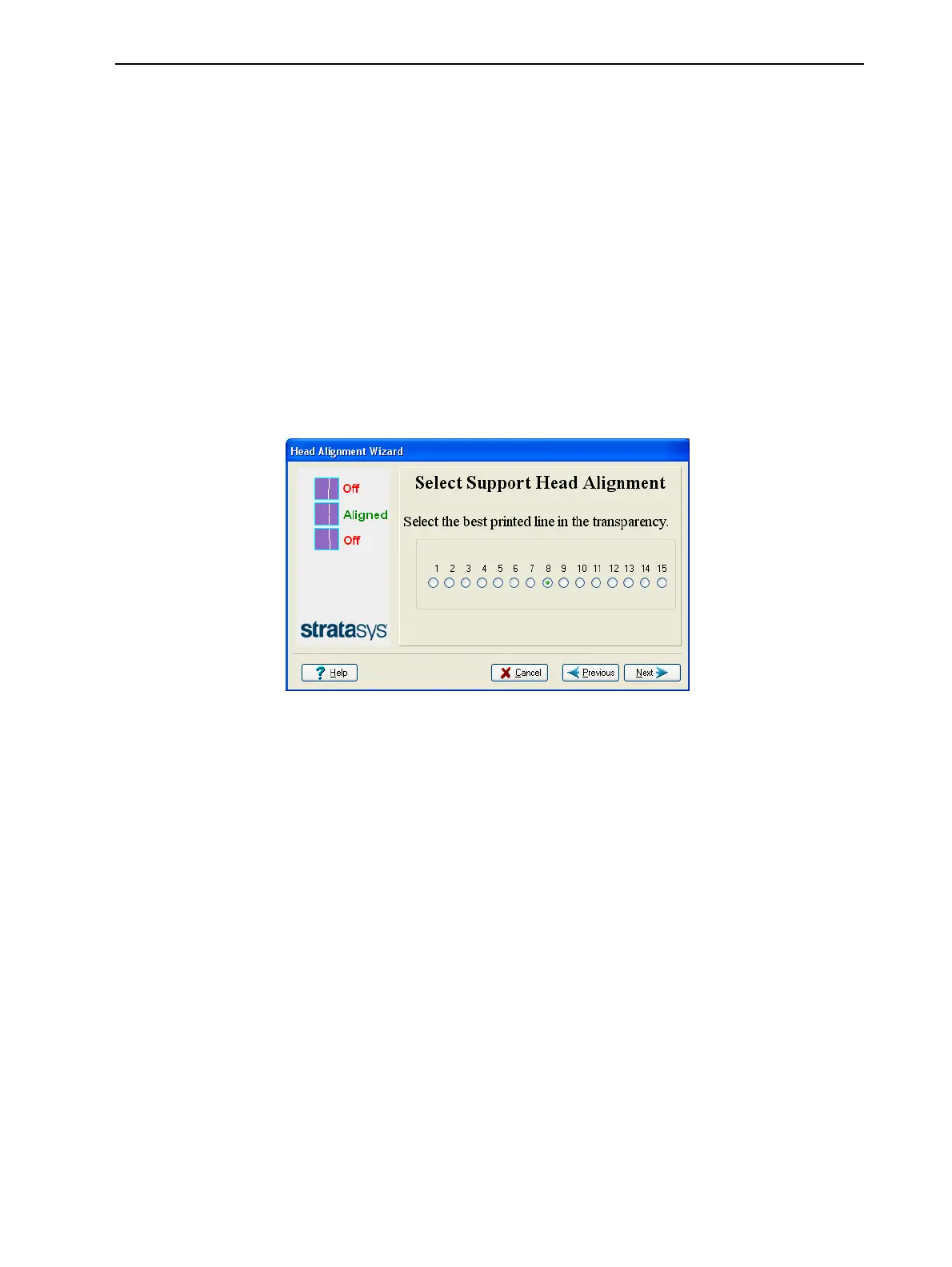
Figure 6-64 Head alignment selection
11. In the head-alignment screen, select the number that indicates which lines
align in the upper and lower rows.
Note: Because the alignment of the middle lines is optimum, the number
“8” is selected, by default, in the wizard screen. This does not change the
head alignment. If you select other numbers, the wizard adjusts the head
alignment, accordingly.
12. Click Next.