102 TimeHub 5500 User’s Guide 097-55501-01 Revision M – January 2009
Chapter 3 Installing the TimeHub 5500
Making Ground and Power Connections
3. Set the switch as appropriate using an 8-inch (20 cm) long screwdriver with a
1/8-inch (3 mm) blade. A small arrow on the rotary switch indicates the selected
setting. Table 3-2 shows the function associated with the rotary switch settings.
– For a Master shelf, set the switch to 0
– For a Remote shelf, set the switch to 7
4. Replace the fuses to power up the shelf.
Making Ground and Power Connections
The TimeHub 5500 operates on voltages between –40 and 57.6 VDC. The shelf has
redundant power input connections labeled A and B, and are located in the
upper-right and upper-left corners of the rear panel. A separate frame ground lug is
provided on the upper corner of the side panel.
TimeHub treatment of the Battery Return (BR) is either Direct Current-Common
(DC-C) or Direct Current-Isolated (DC-I). For the DC-C configuration, the DC return
terminal or conductor is not connected to the equipment frame or the groundings
means of the equipment. For the DC-I configuration, the BR terminal or conductor is
connected to the equipment frame or to the grounding means of the equipment. The
TimeHub is part of a Common Bonding Network (CBN).
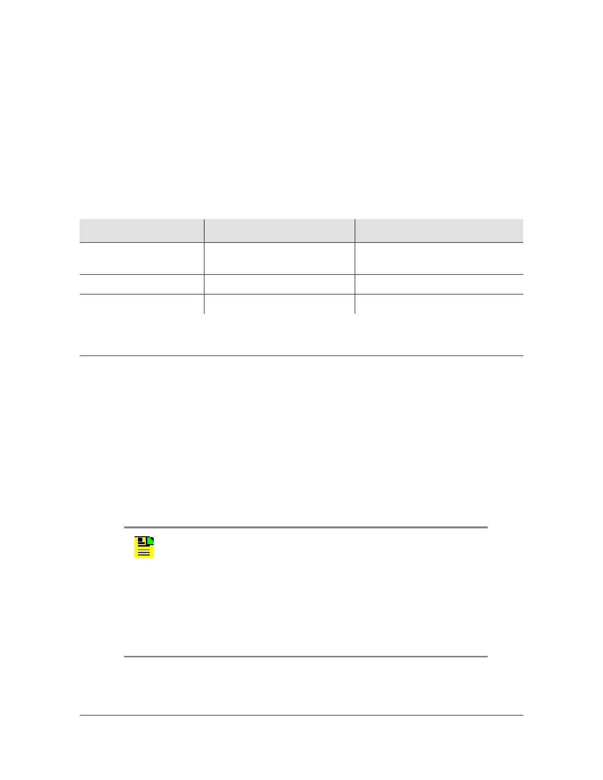
Table 3-2. Master/Remote Rotary Switch Settings and Functions
Rotary Switch Position Function Confirmation
0 (factory setting) Configures the shelf as Master Remote LED does not light
following Warmup
1 – 6 Reserved for future use –
7 Configures the shelf as Remote
Remote LED lights following Warmup
Note: Master shelf CLEI D0MTP0K4RA and above, and expansion
shelf CLEI D0M1X00BRA and above employ frame ground
connection directly to the chassis (reference PCN notifications
00783A1 and 00783B1). Prior to this change, frame ground was
connected to the terminal blocks.
For maintenance on a master shelf prior to CLEI D0MTP0K4RA and
an expansion shelf prior to CLEI D0M1X00BRA, refer to
Maintenance of Prior Master and Expansion Shelves, on page
281.

 Loading...

