097-55501-01 Revision M – January 2009 TimeHub 5500 User’s Guide 61
Chapter 2 Engineering Ordering Information
Card Overview
Input/Alarm Connector Module
The Input/Alarm Connector module (090-55561-01) mounts on the rightmost
position on the rear panel of a Master/Remote shelf. The module is shown in Figure
2-7. Expansion shelves do not use an Input/Alarm Connector module.
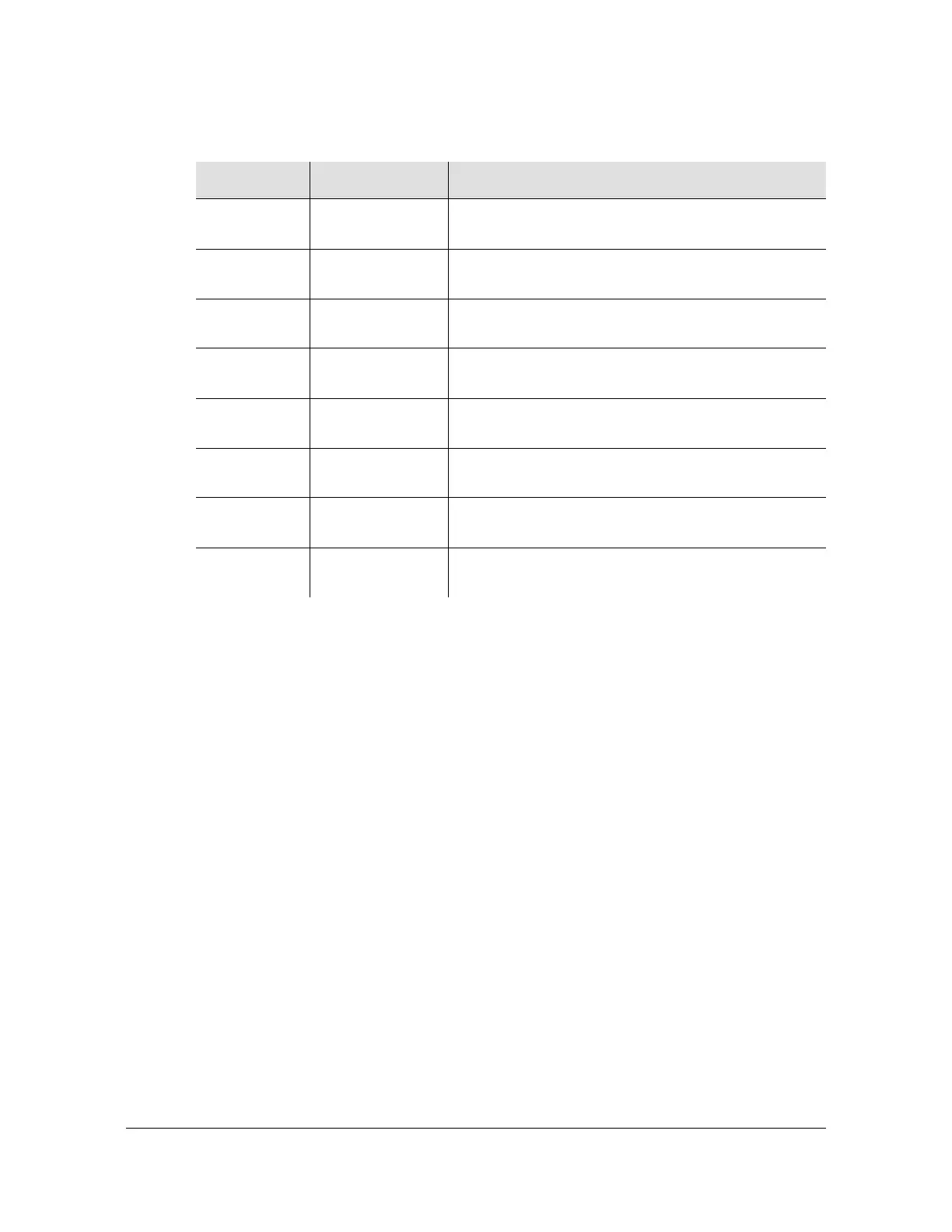
Table 2-8. LEDs on the 5 MHz Output Driver Card Front Panel
Indicator Color Description
PWR Green Off = Power is not present on the card
On = The card is receiving power
FUS Red Off = Fuse is OK
On= Fuse is burned out
ALM Red Off = Card is working without alarms
On = Card is in the alarm state
FAIL Red Off = Card is OK
On = Card failure (component, etc.)
Port On Ch1 Green Off = Port is not active
On = Port is active
Port On Ch2 Green Off = Port is not active
On = Port is active
Port On Ch3 Green Off = Port is not active
On = Port is active
Port On Ch4 Green Off = Port is not active
On = Port is active

 Loading...

