122 TimeHub 5500 User’s Guide 097-55501-01 Revision M – January 2009
Chapter 3 Installing the TimeHub 5500
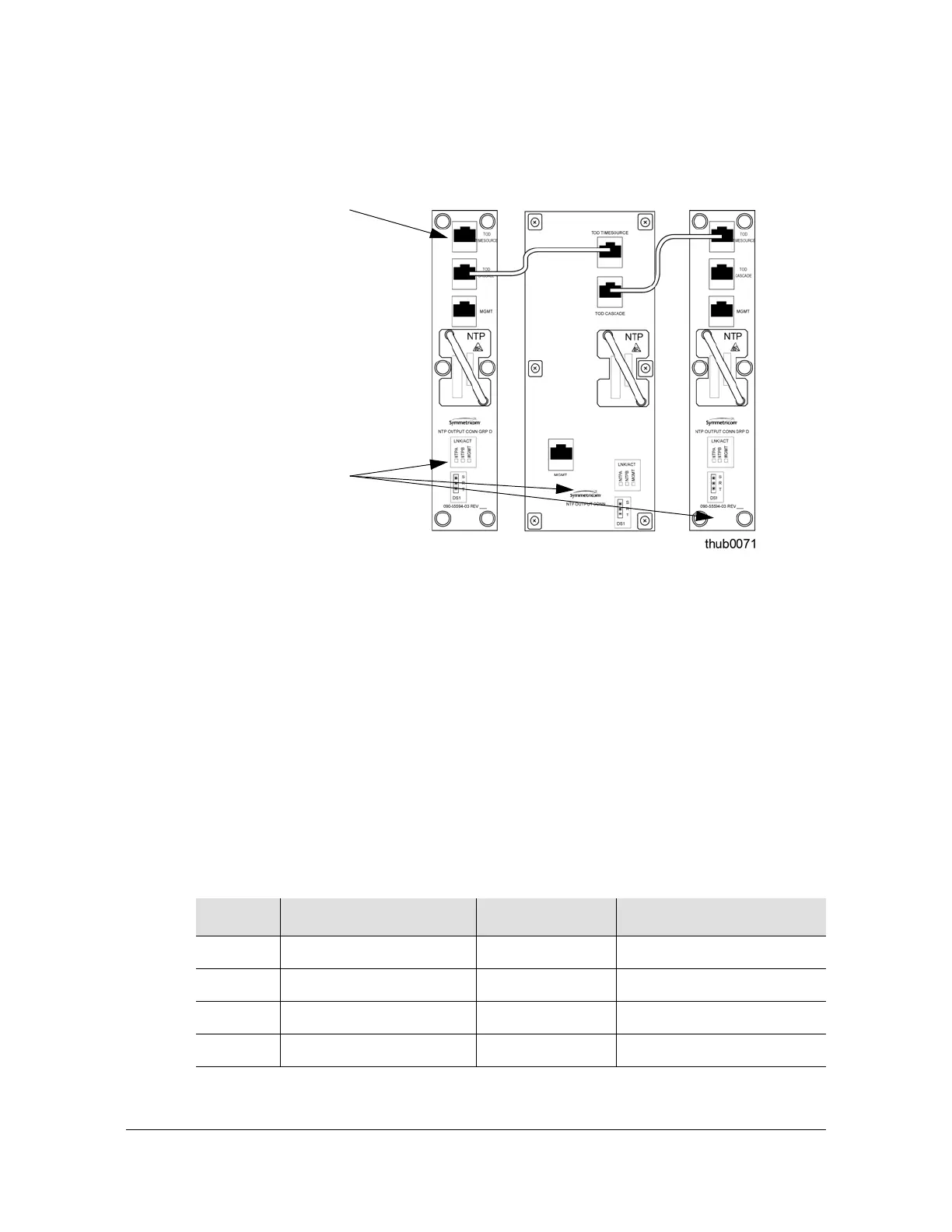
Making Signal Connections
2. Connect the other end of the cable to the TOD TimeSource connector on the next
NTP Output Connector module.
Figure 3-19. Daisy-chaining One Input to Multiple NTP Output Connector Modules
Making Communication Connections
Connecting a LAN Cable
Connect the LAN cable from the network to the RJ-45 (10Base-T) connector labeled
LAN on the rear of the shelf. Refer to Figure 3-13 for the connector location; Table
3-6 describes the connector pinout.
Each TimeHub 5500 has its own IP address that can be set through the local
RS-232 port, as described in Communicating by Ethernet, on page 151. Once the
IP address has been set and a LAN connection made, the TimeHub 5500 can be
remotely accessed on a network.
Table 3-6. Pinout of LAN Connector
Pin Signal Abbreviation Direction
1 Transmit data + TXD +
From TimeHub 5500
2 Transmit data – TXD –
From TimeHub 5500
3 Receive data + RXD +
To TimeHub 5500
6 Receive data – RXD –
To TimeHub 5500
Note: Pins not listed are reserved for future use.
Input from
TimeSource 3x00
TOD Output
NTP Output
Connector modules
installed in Master
or Expansion
shelves

 Loading...

