097-55501-01 Revision M – January 2009 TimeHub 5500 User’s Guide 25
Chapter 1 Description
Functional Overview
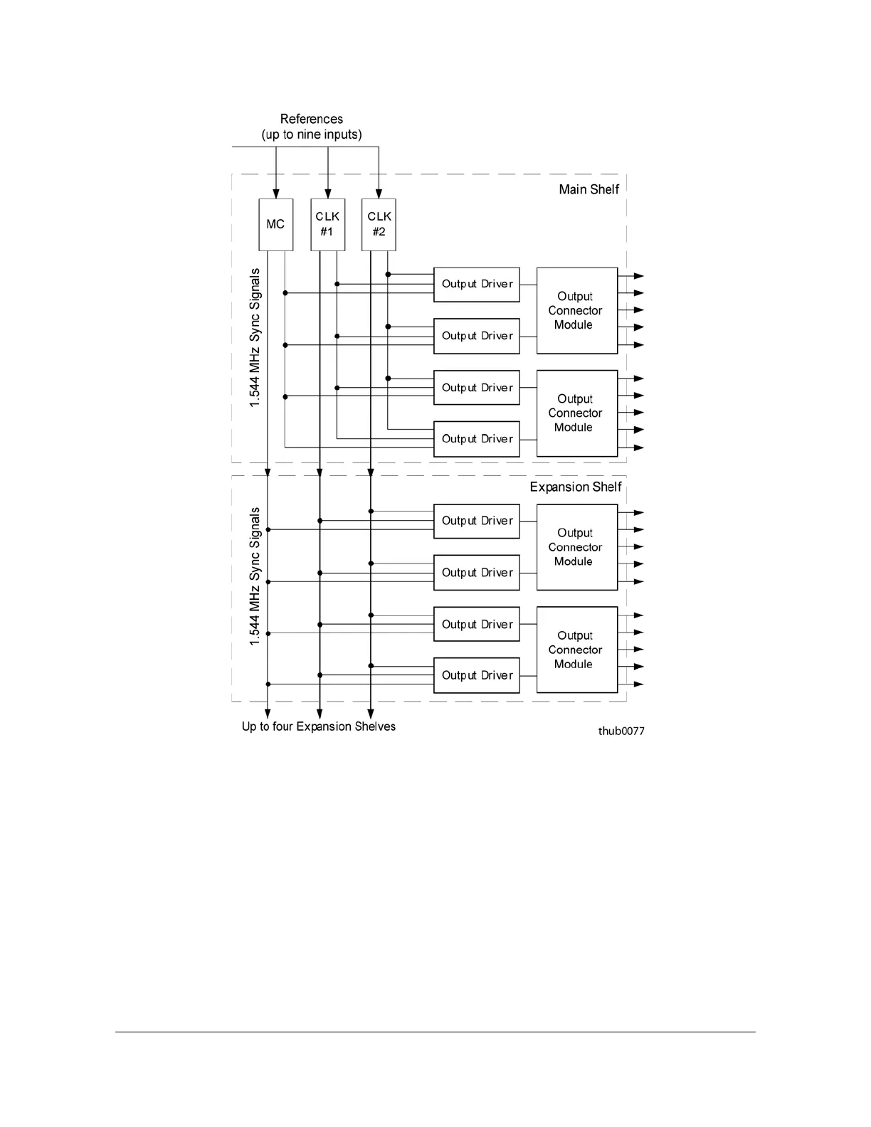
Figure 1-3. General Block Diagram of the TimeHub 5500 System
The Output Driver cards in the Main shelf and any Expansion shelves receive three
1.544 MHz sync signals from the backplane: one from each Clock card and the
passthrough clock from the Management card. The Output Driver cards select one
of these signals based on the Active/Standby status of the Clock Cards. The Output
Driver cards use this signal to derive the output signal types. The Output Connector
modules take the output signal and provide the appropriate connectors and
termination impedances.

 Loading...

