097-55501-01 Revision M – January 2009 TimeHub 5500 User’s Guide 145
Chapter 4 Testing and Configuring the TimeHub
Installing Cards into the Front Panel
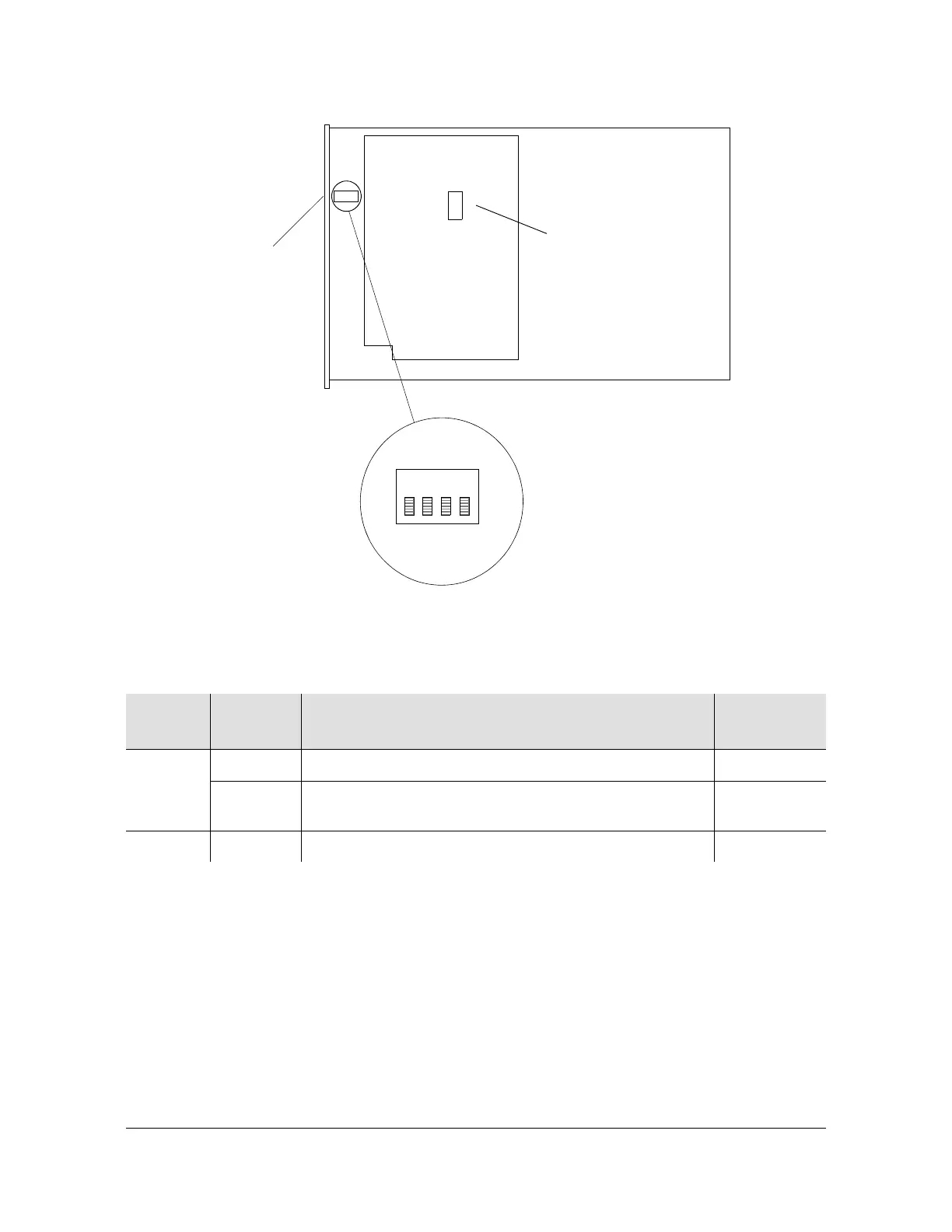
Figure 4-5. Location of Clock Card Switch S1
Confirming the Master or Remote Shelf Setting
To confirm that you have properly set the Master/Remote mode, check the Remote
LED on the front panel of the Clock card after it enters the Freerun mode (the
Freerun LED is lit). The Remote LED lights only if the shelf has been configured for
Remote operation. See Figure 4-4 for the location of the “Remote” LED. You can
also check the setting by issuing the TL1 command MAINCLK (see the TimeHub
5500 TL1 Reference Manual for details).
If the Remote LED responds as expected, the shelf is now properly configured.
Table 4-2. Clock Card S1 Switch Settings
S1
Section
Position Description
Factory
Setting
1 On Normal operation X
Off Mixed oscillator operation. This card contains a
secondary oscillator
–
2-4 On Not used X
4
Note: Switch S1 is shown
Front Panel
S1
2
3
(On)
1
in the factory-set position.
S2 (SW1 on newer cards):
is for factory use only.:

 Loading...

