52 TimeHub 5500 User’s Guide 097-55501-01 Revision M – January 2009
Chapter 2 Engineering Ordering Information
Card Overview
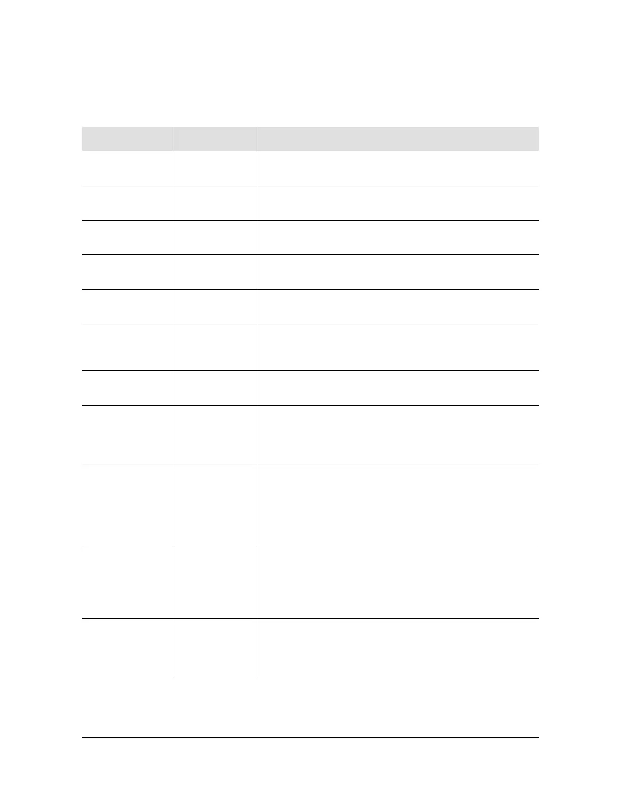
The LED status indicators on the Clock card are described in Figure 2-5.
Table 2-5. Clock Card Front Panel Indicators
Indicator Color Description
Power Green
On = The Clock card is receiving power
Off = No power present
Fuse Red
On = The Clock card fuse is open
Off = The Clock card fuse is not open
Alarm Red
On = An alarm condition is present
Off = No alarm condition is present
Fail Red
On = A hardware or firmware fault has occurred
Off = No hardware or firmware faults have occurred
Warmup Amber
On = Clock card is in Warmup state
Off = Clock card is not in Warmup state
Freerun Red
On = The Clock card is generating an output without
using tracking information from a reference source
Off = The Clock card is not in Freerun state
Tracking Green
On = The Clock card is tracking a qualified input
Off = The Clock card is not tracking a qualified input
Fast Track Green
On = The Clock card has warmed up, is tracking, and is
providing a usable output, but has not yet achieved
Smart Clock (optimal quality) output
Off = The Clock card is not in Fast Track state
SmartClock
Available
Green
On = The system has gathered sufficient information
during tracking to provide Smart Clock (optimal quality)
holdover output if necessary
Off = The system has not gathered sufficient information
during tracking to provide Smart Clock (optimal quality)
holdover output if necessary
Holdover Green
On = All inputs are lost or unacceptable, and the system
is now using the internal oscillator which is using recent
tracking data from a qualified reference to provide the
output
Off = The system is not in Holdover state
Inputs E Green
On = The associated reference input is enabled (E) for
tracking
Off = The associated reference input is not enabled (E)
for tracking

 Loading...

