120 TimeHub 5500 User’s Guide 097-55501-01 Revision M – January 2009
Chapter 3 Installing the TimeHub 5500
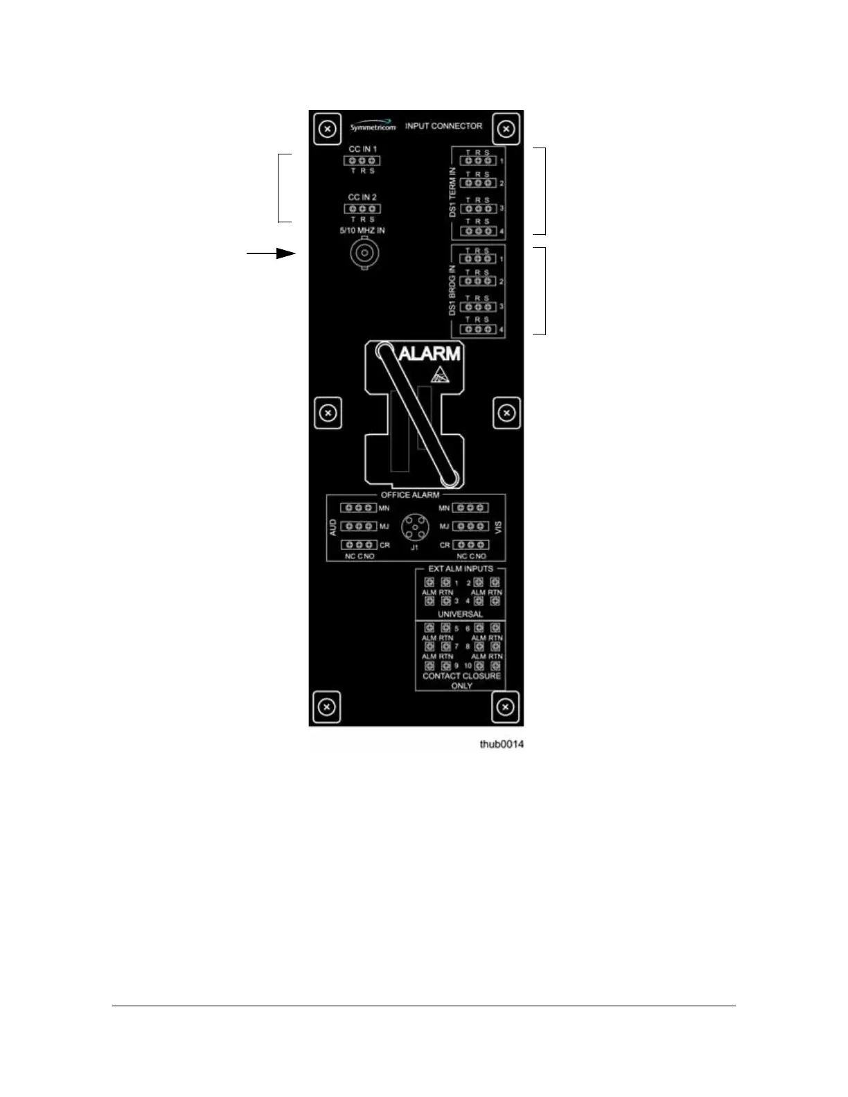
Making Signal Connections
Figure 3-18. Input/Alarm Connector Module Connections
DS1 Monitor
You can connect up to four additional DS1 inputs using the DS1 BRIDG IN pins on
the Input/Alarm Connector module only when you install nine-input Clock cards
(090-55512-02 or 090-55514-02). Connect the tip wire to the pins labeled T, the ring
wire to the pins labeled R, and the shield (if connected at the TimeHub 5500) to the
pins labeled S.
PRS Input
Connect the PRS input to the BNC connector labeled 5/10 MHz IN on the
Input/Alarm Connector module.
PRS input
Composite Clock
(Remote shelf use)
DS1 Reference
DS1 Monitor

 Loading...

