26 TimeHub 5500 User’s Guide 097-55501-01 Revision M – January 2009
Chapter 1 Description
Functional Overview
DS1 and CC Outputs
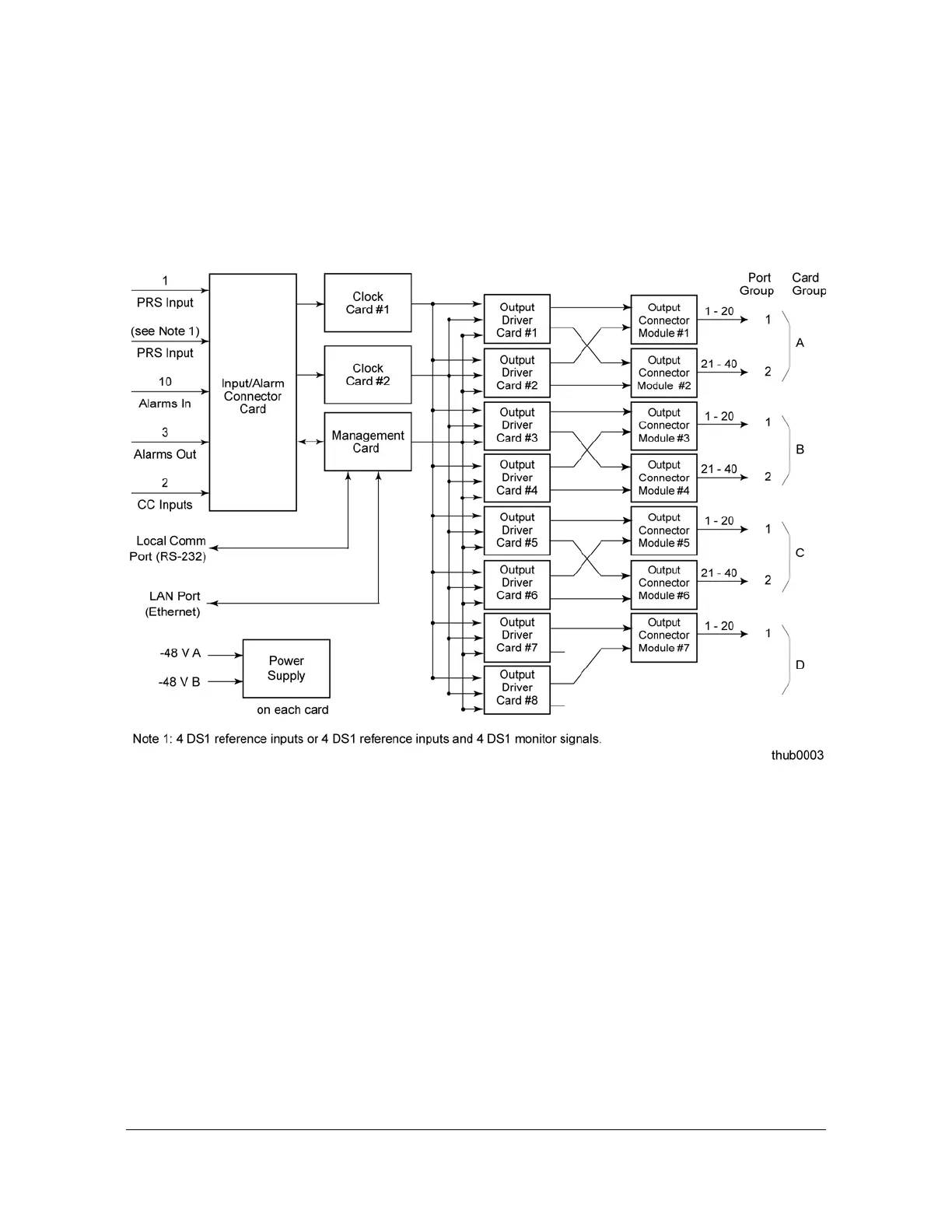
Figure 1-4 shows a block diagram of a TimeHub 5500 Main shelf with redundant
Clock cards and 140 protected outputs. The 1.544 MHz sync signals from each
Clock card and the Management card are connected to Output Driver cards.
Expansion shelves are capable of providing up to 320 protected outputs.
Figure 1-4. Block Diagram for DS1 and CC Outputs
Each DS1/CC Output Driver card can generate a total of 40 outputs: 40 DS1,
40 CC, or 20 of each type. The Output Connector module determines the type of
output signal. There are two output connector card types: DS1 and CC. The master
shelf can accommodate 8 Output Driver modules. With a 1:1 redundancy that most
systems deploy, the main shelf can provide 140 DS1/CC outputs with 1:1
redundancy protection. The reason for providing only 140 and not 160 protected
outputs is that the main shelf only has enough space to accommodate 7 output
connector cards. The outputs are organized into groups of 40; each group is further
divided into 2 port groups of 20 outputs each.
If all reference inputs fail, the system continues to provide timing outputs by using its
internal reference as a source (holdover).

 Loading...

