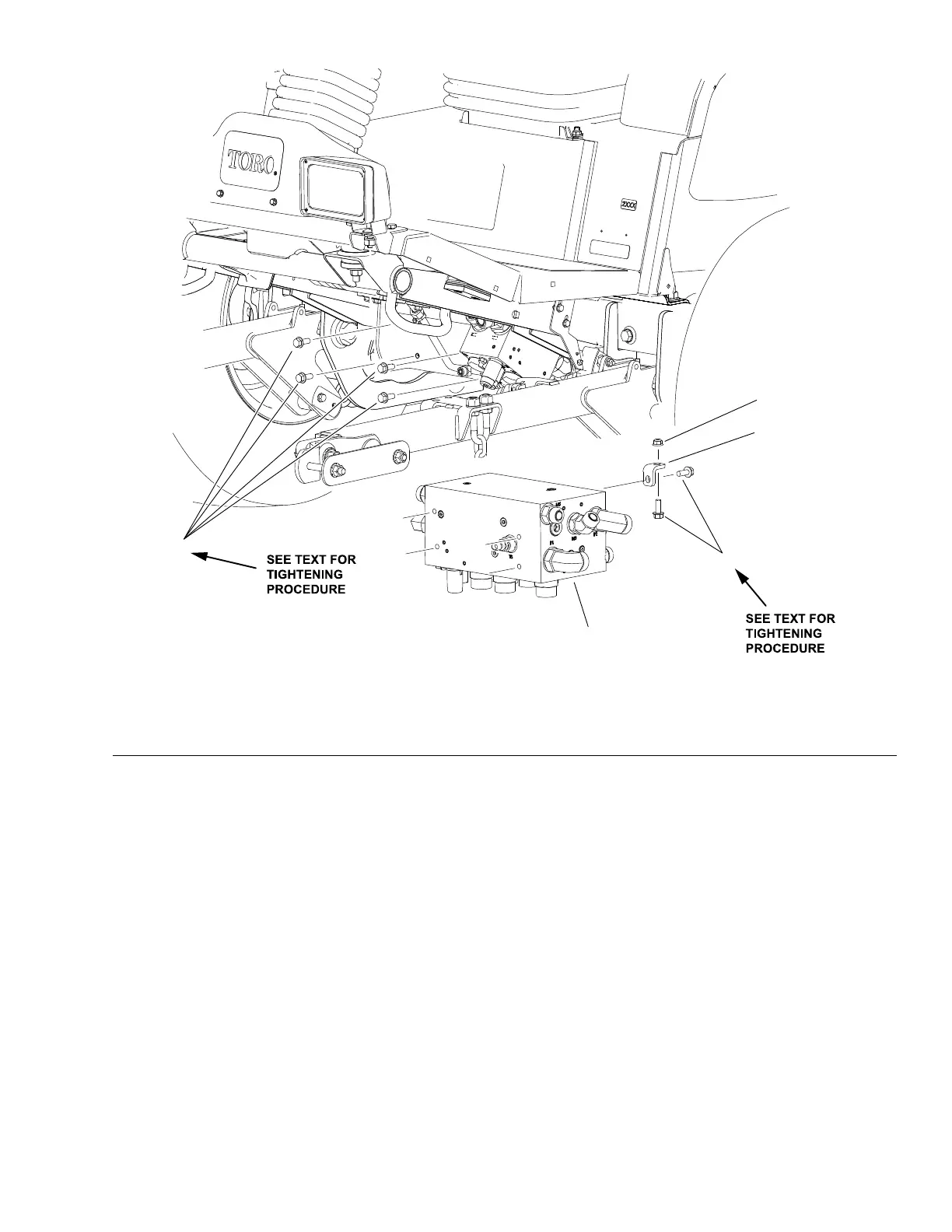
TractionControlManifold
g288015
Figure98
1.Tractioncontrolmanifold
3.Mountingbracket
2.Flangeheadcapscrew(6)
4.Flangenut
Note:Theportsonthetractioncontrolmanifoldaremarkedforeasyidentication
ofcomponents.Example:P1isthepistonpumpconnectionportfortheforward
directionandSVisthelocationforthehigh/lowspeedsolenoidvalve(seeA
HydraulicSchematic(pageA–3)toidentifythefunctionofthehydrauliclinesand
cartridgevalvesateachport).
Groundsmaster
®
5900&5910
Page5–109
HydraulicSystem:ServiceandRepairs
16227SLRevB
 Loading...


