24VoltVoltageDivider
g288621
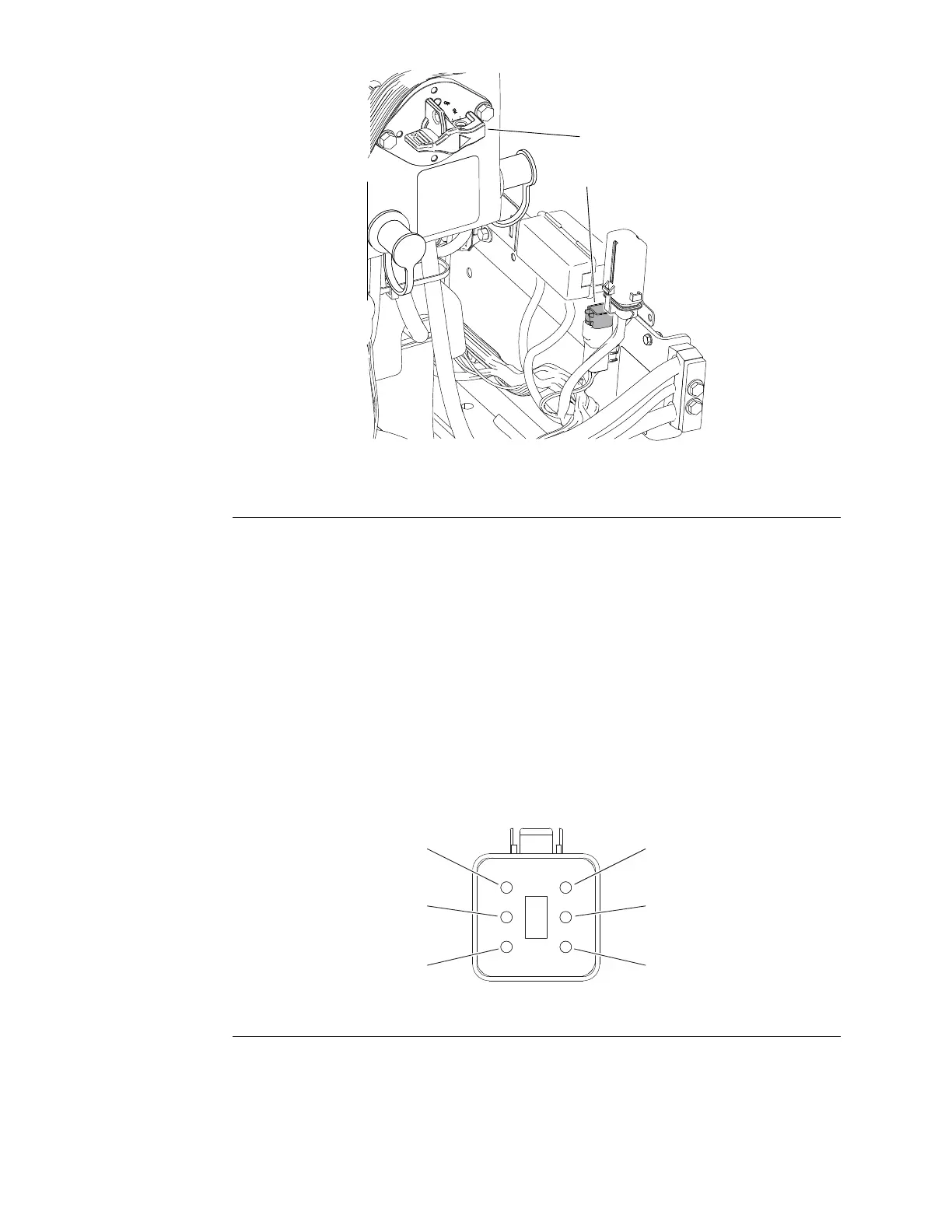
Figure273
1.Battery−disconnectswitch2.Voltagedivider
24VoltelectricalsystemactivityismonitoredasaninputtothemasterTEC.A
voltagedividerinthecircuitreducesthe24VoltsystemvoltagefortheTECinput
signaltoapproximately4VDC.TheTECusesthereducedsignalvoltageto
calculatethe24Voltsystemvoltage.Thevoltagedividerislocatedintherear
powercenterintherightrearcorneroftheenginecompartment(Figure273).
Testing
1.Parkthemachineonalevelsurface,lowerthecuttingunitsandstopthe
engine.Removethekeyfromthekeyswitch.
2.Turnbattery−disconnectswitchtotheOFFposition.
3.Locatethevoltagedividerandunplugitfromtherearwireharnessfortesting.
4.Thevoltagedividercanbetestedusingadigitalmultimeter(ohmssetting)
andthetabletotheright.Replacethevoltagedivideriftestingdetermines
thatitisfaulty.
g288622
Figure274
5.ThevoltagedividerterminalsaremarkedasshowninFigure274.Withthe
useofamultimeter(ohmssetting)thedividermaybetestedtodetermine
whethereachottheinternalresistorsinthedividerisfunctioningproperly
(showninbelowtable).
Note:Voltagedividerterminals2and5arenotused.
ElectricalSystem:ComponentTesting
Page6–132
Groundsmaster
®
5900&5910
16227SLRevB
 Loading...


