BlowerFan
g299935
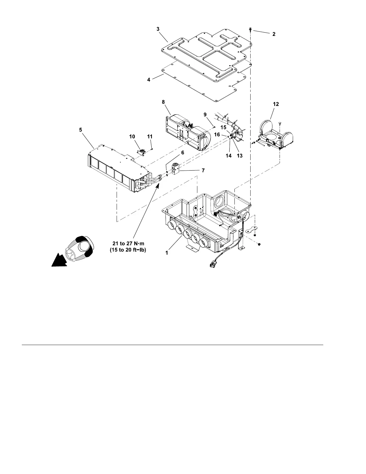
Figure354
1.Mixingbox7.Expansionvalve
13.A/Chose(fromdrier−receiver)
2.Rivet(19)
8.Blowerfan14.O−ring
3.Mixingboxcover
9.Screw(6)15.A/Chose(toACcompressor)
4.Coverinsulation
10.Freezeswitch
16.O−ring
5.HeatercoreA/Cevaporator
assembly
11.Screw(2)
6.O−ring(2)
12.Airdiverterassembly
Note:Theblowerfancanberemovedandinstalledwiththemixingbox(item1
inFigure354)attachedtothecabheadliner.
Removal(Figure354)
1.Parkmachineonalevelsurface,lowercuttingdecksandstopengine.
Removekeyfromthekeyswitch.
2.Toaccessblowerfan,removeroofpanelfromtopofcab(seeRoofAssembly
(page9–9)).
3.ReadtheGeneralPrecautionsforRemovingandInstallingAirConditioning
SystemComponents(page9–4).
OperatorCab:ServiceandRepairs
Page9–26
Groundsmaster
®
5900&5910
16227SLRevB
 Loading...


