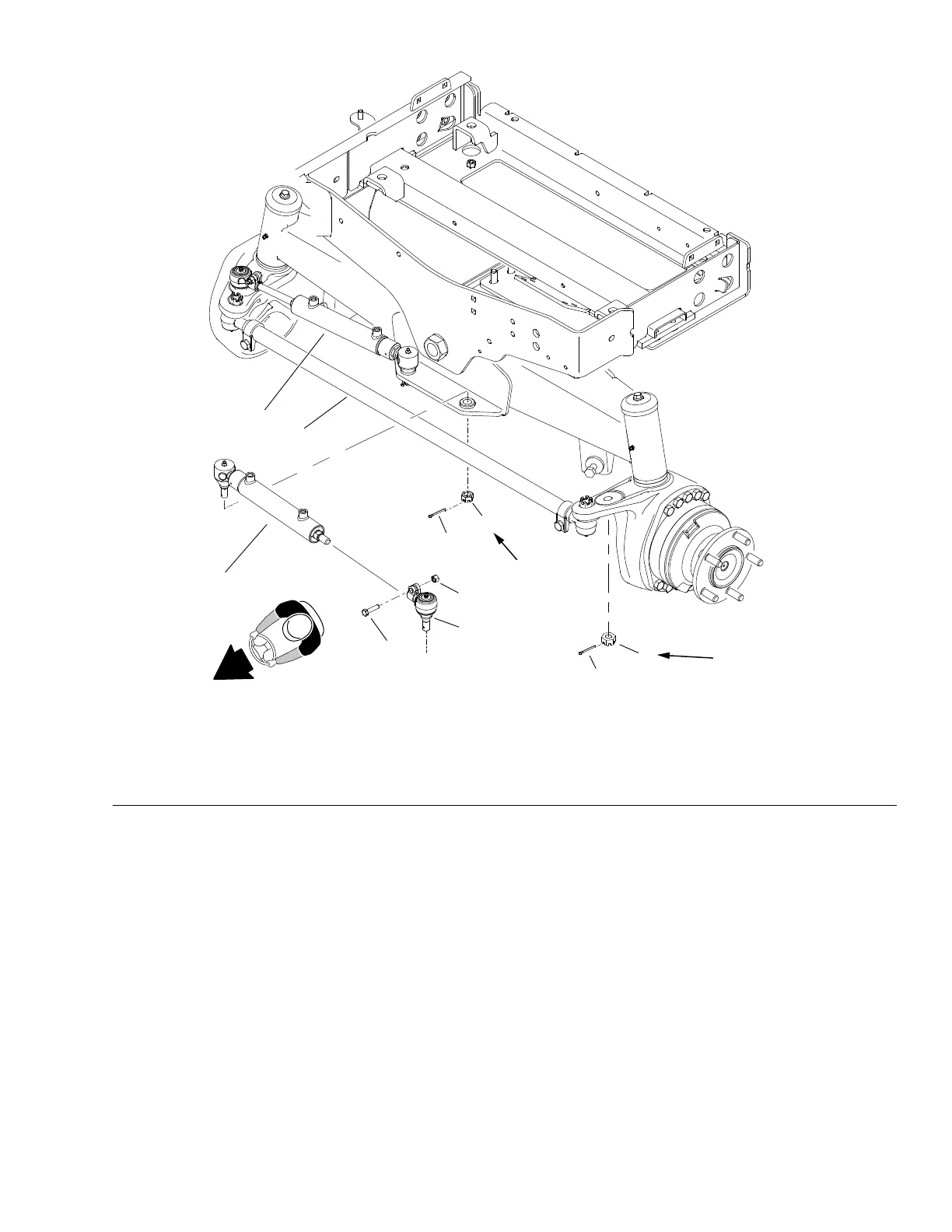
SteeringCylinders
40 to 61 N·m
(30−to 45 ft−lb)
40 to 61 N·m
(30−to 45 ft−lb)
1
1
2
3
4
5
5
6
6
7
g288164
Figure123
1.Steeringcylinder4.Capscrew
7.Tierodassembly
2.Balljoint
5.Slottedhexnut
3.Locknut
6.Cotterpin
SteeringCylinderRemoval(Figure123)
1.Parkmachineonalevelsurface,lowercuttingdecksfully,disengagePTO
andstopengine.Removekeyfromthekeyswitch.
2.ReadtheGeneralPrecautionsforRemovingandInstallingHydraulicSystem
Components(page5–73).
3.Topreventcontaminationofhydraulicsystemduringsteeringcylinder
removal,thoroughlycleanexteriorofcylinder,ttingsandhoses.
Note:T oeaseassembly,labelallhydraulichosestoidentifytheircorrect
positiononthesteeringcylinder.
4.Disconnecthydraulichosesfromsteeringcylinderttings.Putcapsorplugs
onttingsandhosestopreventcontamination.Taghydrauliclinesforproper
assembly.
5.Removecotterpinsandslottedhexnutsthatsecurethecylinderballjointsto
rearaxleandsteeringspindle.
Groundsmaster
®
5900&5910
Page5–139
HydraulicSystem:ServiceandRepairs
16227SLRevB
 Loading...


