SteeringCylinderService
11
12
13
14
15
17
16
18
1
2
3
4
5
6
7
8
9
10
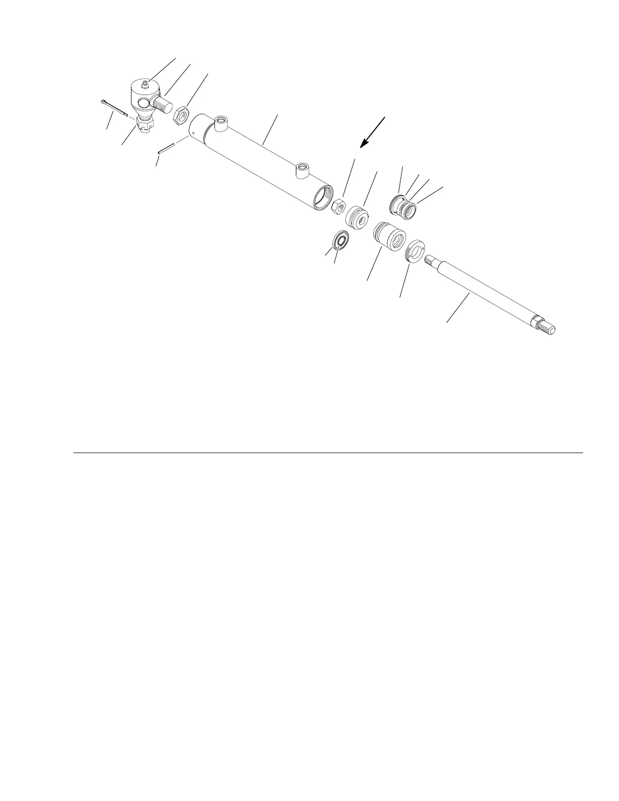
54 N·m
(40 ft−lb)
g288165
Figure124
1.Balljoint7.Barrel
13.O−ring
2.Greasetting
8.Locknut14.Back−upring
3.Jamnut9.Piston15.Rodseal
4.Cotterpin
10.Pistonseal16.Rodwiper
5.Castlenut11.O−ring
17.Internalcollar
6.Rollpin12.Head18.Pistonrod
SteeringCylinderDisassembly(Figure124)
1.Removeoilfromsteeringcylinderbyslowlypumpingthepistonrod.After
removingoilfromcylinder,plugbothportsandthoroughlycleantheoutside
ofthecylinder.
2.Removeinternalcollar(item17)thatsecuresheadinbarrel.
3.Graspendofpistonrodanduseatwistingandpullingmotiontocarefully
extractpiston,pistonrodandheadfromcylinderbarrel.
4.Usingawrenchonthepistonrodatstopreventtherodfromturning,remove
locknut(item8)fromrod.Removepistonandheadfromrod.
5.RemoveallsealsandO−ringsfromheadandpiston.
6.Washpartsincleansolvent.Drypartswithcompressedair.Donotwipeparts
drywithpapertowelsorcloth.Lintinahydraulicsystemwillcausedamage.
7.Carefullyinspectinternalsurfaceofbarrelfordamage(deepscratches,
out−of−round,etc.).Replaceentirecylinderifbarrelisdamaged.Inspect
pistonrodandpistonforevidenceofexcessivescoring,pittingorwear.
Replaceanydamagedparts.
8.Ifpistonrodballjointremovalisnecessary,loosencapscrewandlocknut
andthenunscrewballjointfrompistonrod.
Groundsmaster
®
5900&5910
Page5–141
HydraulicSystem:ServiceandRepairs
16227SLRevB
 Loading...


