SteeringCylinderDisassembly(Figure124)(continued)
9.Ifnecessary,removebarrelendballjoint(item1)frombarrelasfollows:
A.Loosenjamnut(item3).
B.Driverollpin(item6)frombarrel.
C.Unscrewballjointfrombarrel.
SteeringCylinderAssembly(Figure124)
1.Useacompleterepairkitwhenrebuildingthecylinder.Putacoatingofclean
hydraulicoilonallnewsealsandO−rings.
2.InstallnewO−ringsandsealtothepistonandnewO−ring,back−upring,rod
sealandrodwipertohead.
3.Lubricateshaftwithcleanhydraulicoil.Slideheadandpistonontopistonrod.
4.Usingawrenchonthepistonrodatstopreventtherodfromturning,install
andtightenlocknut(item8).Torquelocknutto54N·m(40ft−lb).
5.Putacoatingofcleanhydraulicoilonallcylinderpartstoeaseassembly.
6.Carefullyslidepistonrodassemblyintocylinderbarreltakingcaretonot
damagesealsorO−rings.
7.Secureheadinbarrelwithinternalcollar.
8.Ifbarrelendballjoint(item2)wasremoved,installballjointtobarrelas
follows:
A.Threadballjointintobarrelsothatrollpinholeinjointalignswithhole
inbarrel.
B.Driverollpinintoalignedholesinbarrelandballjoint.
C.Tightenjamnut.
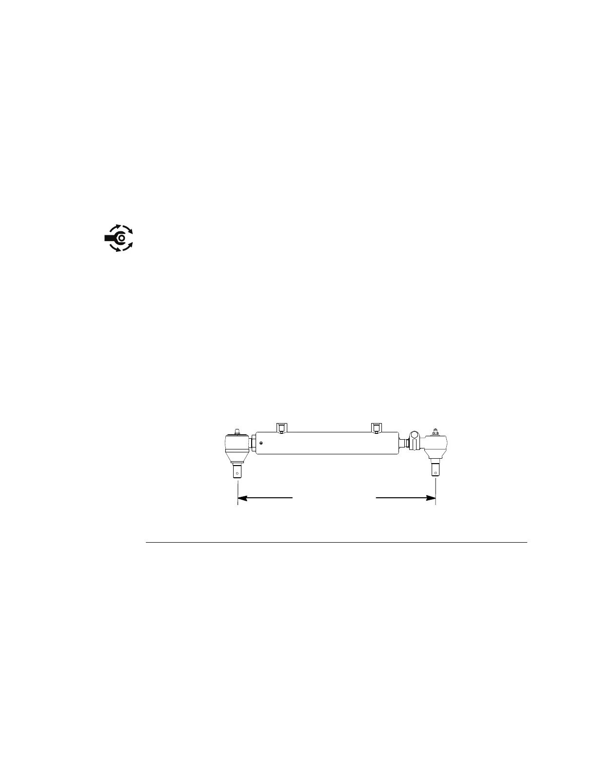
35.5 to 37.0 cm
(14.0 to 14.6 in)
g288166
Figure125
9.Ifpistonrodendballjointwasremoved,fullyretractpistonrodandthread
balljointontorodsothatcentertocenterlengthisfrom35.5to37.0cm(14.0
to14.6in)(Figure125).Orienttheheadoftheballjointclampscrewtoward
thefrontofthemachineandtightentheclampscrewandlocknut.
HydraulicSystem:ServiceandRepairs
Page5–142
Groundsmaster
®
5900&5910
16227SLRevB
 Loading...


