CuttingDeckControlManifolds
g288131
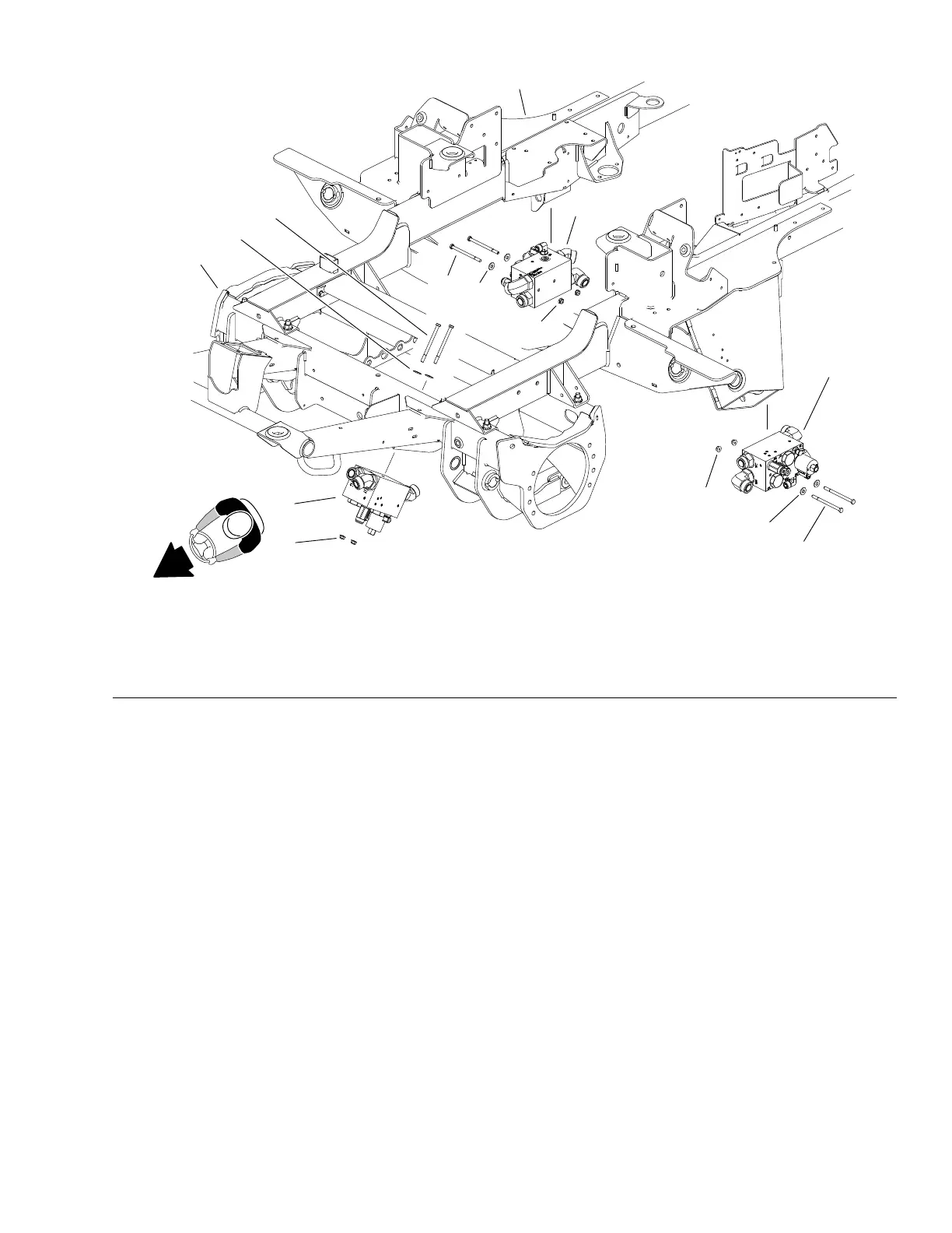
Figure110
1.FrontDeckcontrolmanifold4.Capscrew(6)7.Mainframe
2.RHDeckcontrolmanifold5.Flatwasher(6)8.Frontaxleframe
3.LHDeckcontrolmanifold6.Flangenut(6)
Thecontrolmanifoldsforthethreecuttingdecksectionsareverysimilar.
Note:Whenservicingthecontrolmanifolds,DONOTinterchangepartsfrom
onecontrolmanifoldtoanother.
Note:Theportsonthecuttingdeckcontrolmanifoldsaremarkedforeasy
identicationofcomponents.Example:PRVistheproportionalreliefvalveand
M2isthereturnowfromthedeckmotor.SeeAHydraulicSchematic(pageA–3)
toidentifythefunctionofthehydrauliclinesandcartridgevalvesateachport.
CuttingDeckControlManifoldRemoval(Figure110)
1.ReadtheGeneralPrecautionsforRemovingandInstallingHydraulicSystem
Components(page5–73).
2.Topreventcontaminationofhydraulicsystemduringmanifoldremoval,
thoroughlycleanexteriorofmanifoldandttings.
3.Disconnectwireharnessconnectorfromtheproportionalreliefvalvesolenoid.
4.Disconnecthydrauliclinesfrommanifoldandputcapsorplugsonopen
hydrauliclinesandttings.Labeldisconnectedhydrauliclinesforproper
assembly.
5.Supportthecuttingdeckcontrolmanifoldtopreventitfromfalling.
6.Removetwo(2)capscrews,atwashersandangenutsthatsecure
manifoldtoframeandremovethecontrolmanifoldfromtheframe.
Groundsmaster
®
5900&5910
Page5–125
HydraulicSystem:ServiceandRepairs
16227SLRevB
 Loading...


