CuttingDeckMotorRemoval(Figure104)(continued)
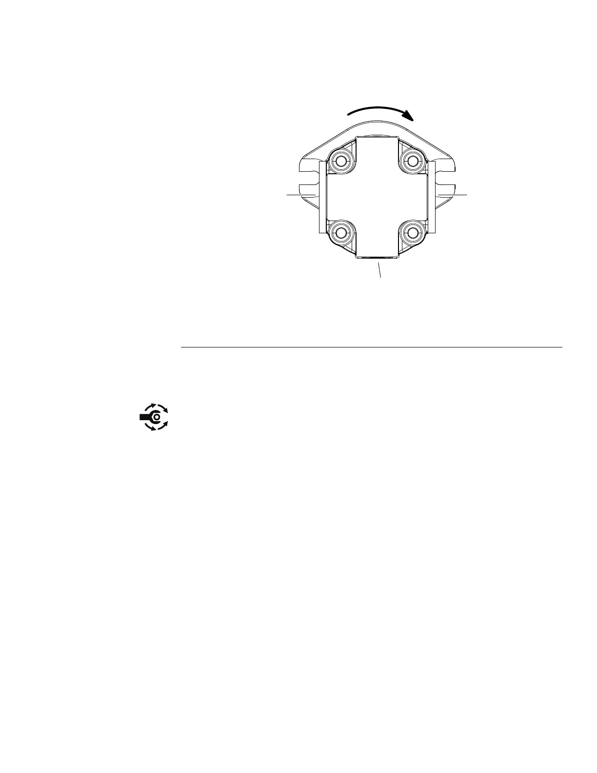
8.Ifrequired,removehexnutandwasherthatsecurecouplerhubtomotor
shaft.Usesuitablepullertoremovehubfromshaft.Removewoodruffkey.
CuttingDeckMotorInstallation(Figure104)
g288022
Figure105
1.Flow−in
3.Casedrain
2.Flow−out
1.Ifttingswereremovedfromdeckmotor,lubricateandplacenewO–rings
ontottings.Installttingsintomotorportsusingmarksmadeduringthe
removalprocesstoproperlyorientatettings.Tightenttings(seeInstalling
theHydraulicFittings(SAEStraightThreadO-RingFittings)(page5–9)).
2.Ifremoved,installwoodruffkeyandcouplerhubtomotorshaft.Securewith
washerandhexnut.Tightenhexnutfrom37to44N·m(27to33ft−lb).
3.Positionspider(item12)inspindlepulley.Aligncouplerhubonmotor
shaftwithspiderandplacedeckmotoronthemotormount.Makesurethe
shoulderofthedeckmotortssquarelyinsidethemotormountopening.
4.Securemotortocuttingdeckwithtwo(2)angeheadscrews.
Note:MakesureIN/OUThydraulichosesareattachedtocorrectdeckmotor
portsordeckbladeswillspinbackwards.
5.Removecapsorplugsfromhydraulicttingsandhoses.Uselabelsattached
duringremovalandconnecthydraulichosestodeckmotor(seeInstalling
HydraulicHosesandTubes(O-RingFaceSeal)(page5–7)).
6.Makesurehydraulictankisfull.Addcorrectoilifnecessary.
7.Afterassemblyiscompleted,raiseandlowercuttingunitsandverifythat
hydraulichosesandttingsarenotcontactedbyanymovingcomponents.
8.Checkhydraulicsystemforleaksbeforereturningthemachinetoservice.
Groundsmaster
®
5900&5910
Page5–119
HydraulicSystem:ServiceandRepairs
16227SLRevB
 Loading...


