BatteryRemoval(continued)
g288672
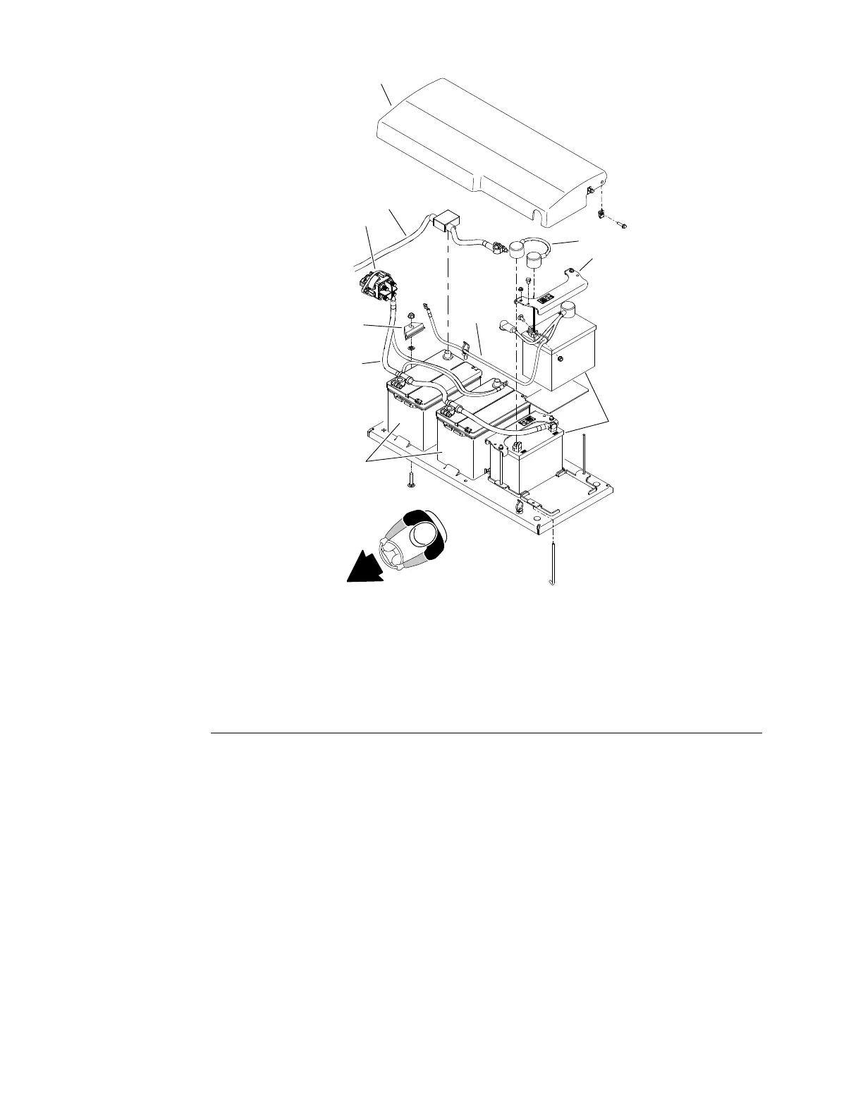
Figure282
1.Batterycover
6.Cableassembly(for24VDCsystem)
2.Battery−disconnectswitch
7.Cable−jumper(for24VDCsystem)
3.Batteries−12voltfor12VDCsystem)(2)8.Ground(−)cable
4.Batteries−12voltfor24VDCsystem)(2)9.Batteryholddown(2)
5.Positive(+)cable(for12VDCsystem)10.Batteryholddown(2)
BatteryInstallation
1.Securebatterieswithholddowns.
2.Installbatterycables.
3.Positionbatterycoverinplaceandsecurewithremovedfasteners.
4.Installrearshroud(Figure281).
5.Installsideshrouds(Figure280).
6.Raiserearbumperintopositionandinstallangeheadscrews.Tightenall
angeheadscrewssecuringrearbumpertoframe(Figure279).
7.Turnthebattery−disconnectswitchtotheONpositionbeforereturningthe
machinetoservice.
ElectricalSystem:ServiceandRepairs
Page6–142
Groundsmaster
®
5900&5910
16227SLRevB
 Loading...


