Function of the digital inputs / outputs; MD-300
TR-Electronic GmbH 2008, All Rights Reserved Printed in the Federal Republic of Germany
Page 214 of 252 TR - EMO - BA - DGB - 0019 - 08 06/06/2019
9.2 Function assignment
9.2.1 Inputs
About this 4-byte parameter P807 “Digital IN Function”, to the 4 digital inputs different functions can be
assigned. For each input one byte is reserved:
Table 27: Structure of the parameter 807 “Digital IN Function”
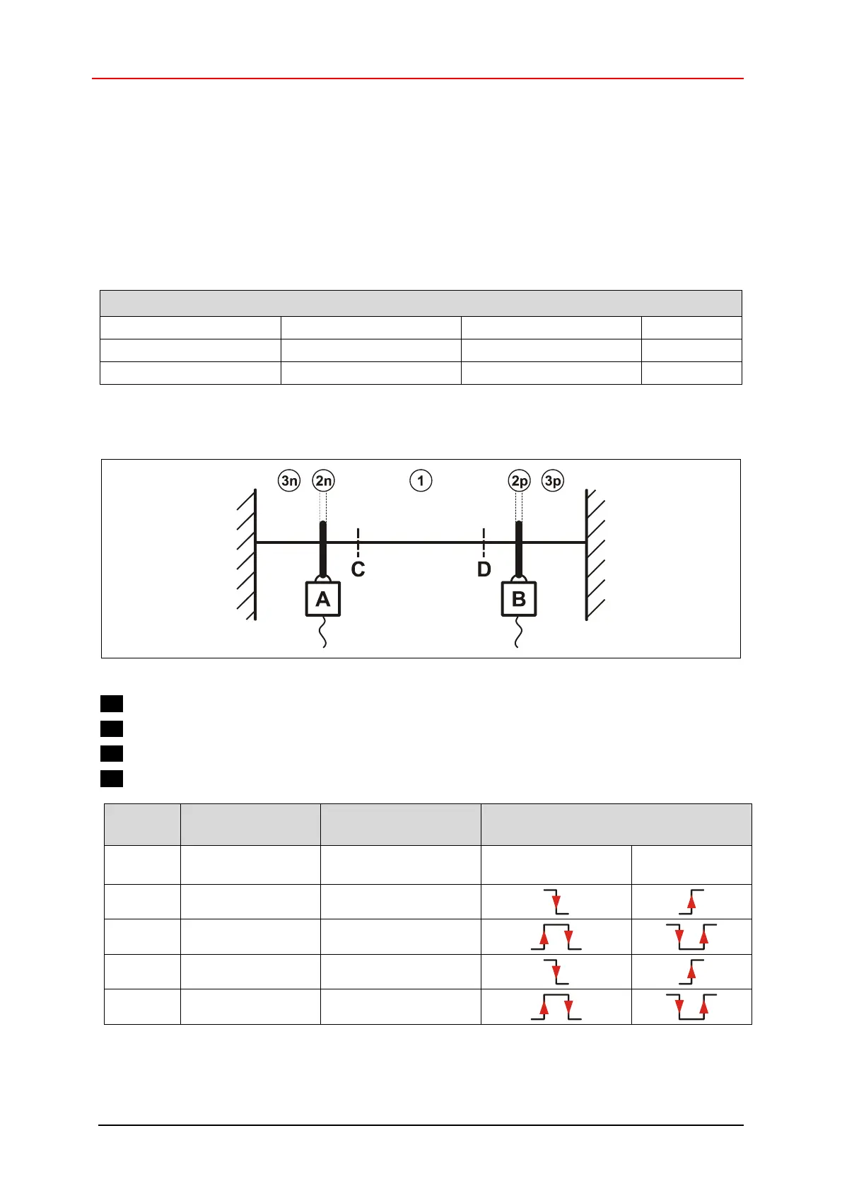
9.2.1.1 Implementation of the hardware limit switch function
Figure 20: Functional principle of the hardware limit switches
A: Negative limit switch
B: Positive limit switch
C: Negative soft limit switch
D: Positive soft limit switch
permissible
movement direction
1)
required edge sequence,
to return to 1
permissible
movement direction
1)
only possible, if the fault P947 “Hardware limit switch reached” with fault number 580/581 was
acknowledged.