Remote TCP
Waypoint
Similar to regular waypoints, RTCP Waypoints allow a tool to move linearly
using constant speed and circular blends. The default blend radius size is a
shared value between all the waypoints. A smaller blend radius size
sharpens the path turn. A larger blend radius size smoothens the path.
RTCP Waypoints are taught by physically moving the Robot Arm to a
desired position.
Teaching Remote
TCP Waypoints
1. In the Program Tab, insert an RTCP_MoveP node.
2. On the RTCP_MoveP node, tap Set to bring up the Move screen.
3. On the Move screen, use Teach Mode or Jog to position the robot in
a desired configuration.
4. Tap the green check mark to validate.
Configuring an
RTCP Waypoint
Use blends to enable the robot to smoothly transition between two
trajectories. Tap Use Shared Blend Radius or tap Blend with radius to set
the blend radius for a waypoint from an RTCP_MoveP.
NOTICE
A physical time node (e.g. Move, Wait) cannot be used as
a child of an RTCP_MoveP node. If an unsupported node
is added as a child to an RTCP_MoveP node, the program
fails to validate.
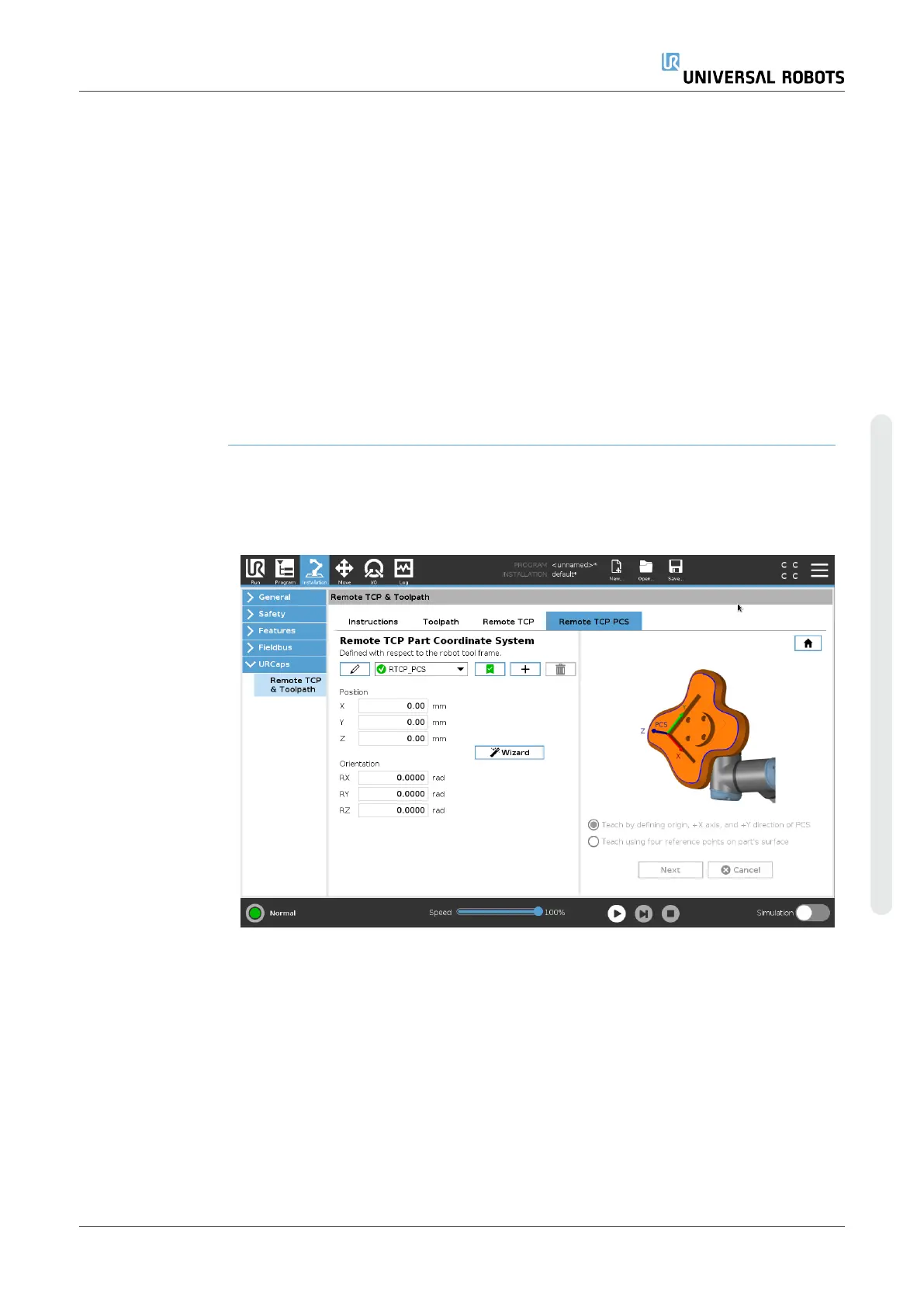
Remote TCP
Toolpath
The Remote TCP and Toolpath URCap generates robots motions
automatically, making it easier to follow complex trajectories accurately.
User Manual 273 UR16e
Copyright © 2009–2024 by UniversalRobotsA/S. All rights reserved.