July, 2007
4-96
WorkCentre 5020
ADJ 10.3.1
Initial Issue
Repairs and Adjustments
ADJ 10.3.1 IIT Lead Edge/Side Edge Registration
Purpose
To obtain the home position in the IIT lead edge (slow scan)/IIT side edge (fast scan) direction.
Check
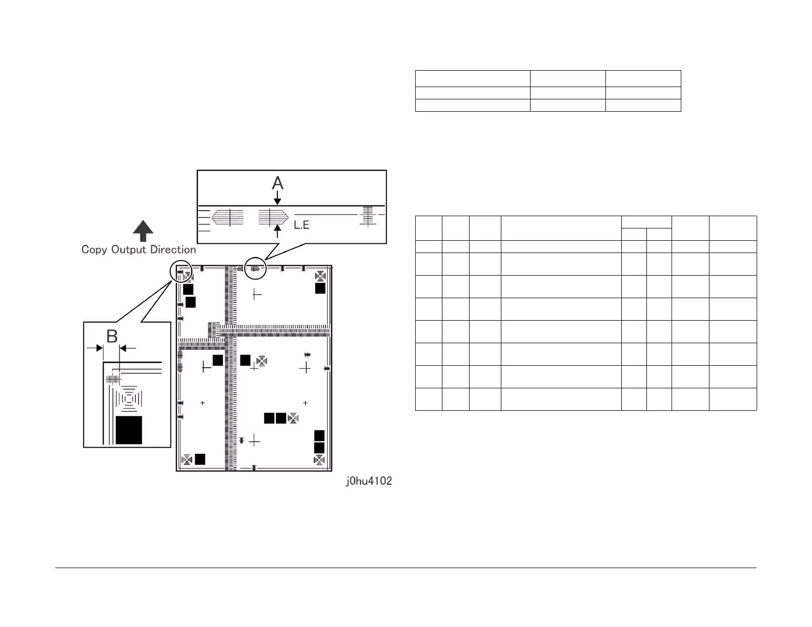
1. Set the Test Pattern 499T247 (A3) on the platen, so that there is no gap between it and
the Rear Registration Guide. Make 3 copies using 100% R/E and A3 SEF paper.
2. Measure the lead edge and side edge of the 3rd copy (Figure 1).
Lead edge: part A in the figure
Side edge: part B in the figure
Figure 1 IIT Lead Edge/Side Edge Registration
3. Check that the measured values for lead edge (A) and side edge (B) meet the specifica-
tions of the corresponding mode.
Adjustment
1. Enter the Diagnostic Mode, and use the following Chain Functions to perform adjustments
until the measured values for lead edge (A) and side edge (B) registration are within the
specifications.
When the measured value is short, reduce the setting value.
When the measured value is long, increase the setting value.
2. After the adjustment, again set the Test Pattern 499T247 (A3) on the platen so that there
is no gap between it and the Rear Registration Guide. Make a copy using 100% R/E and
A3 SEF paper.
3. Repeat the procedure until the measured values for lead edge (A) and side edge (B) are
within the specifications.
Table 1 Specification
Item Simplex MSI
Lead edge (A) 10 1.6mm 10 2.2mm
Side edge (B) 5 2.1mm 5 3.0mm
Table 2
Chain Func Sub
System
Name Value Initial
Value
1 Count
Min. Max.
20 1 PH REGI ADJUSTMENT - ALL 0 60 30 0.146mm
20 41 PH TRAY 1 for Normal LEAD REGI
ADJ
0 60 30 0.146mm
20 42 PH TRAY 2 for Normal LEAD REGI
ADJ
0 60 30 0.146mm
20 43 PH MSI for Normal LEAD REGI
ADJ
0 60 30 0.146mm
6 20 ROS ALL TRAY - LASER SIDE REGI
ADJUSTMENT
1 99 50 0.254mm
6 21 ROS TRAY 1 - LASER SIDE REGI
ADJUSTMENT
1 99 50 0.254mm
6 22 ROS TRAY 2 - LASER SIDE REGI
ADJUSTMENT
1 99 50 0.254mm
6 26 ROS MSI - LASER SIDE REGI
ADJUSTMENT
1 99 50 0.254mm
 Loading...