5-44
POWR
E
CRANKSHAFT AND PISTON/
CONNECTING ROD ASSEMBLY
Measuring steps
CAUTION:
Install the bearings in their original posi-
tions. Incorrect oil clearance measurements
can lead to engine damage.
(1) Clean the bearings and bearing por-
tions of the connecting rod.
(2) Install the upper half of the bearing
into the connecting rod and the lower
half into the connecting rod cap.
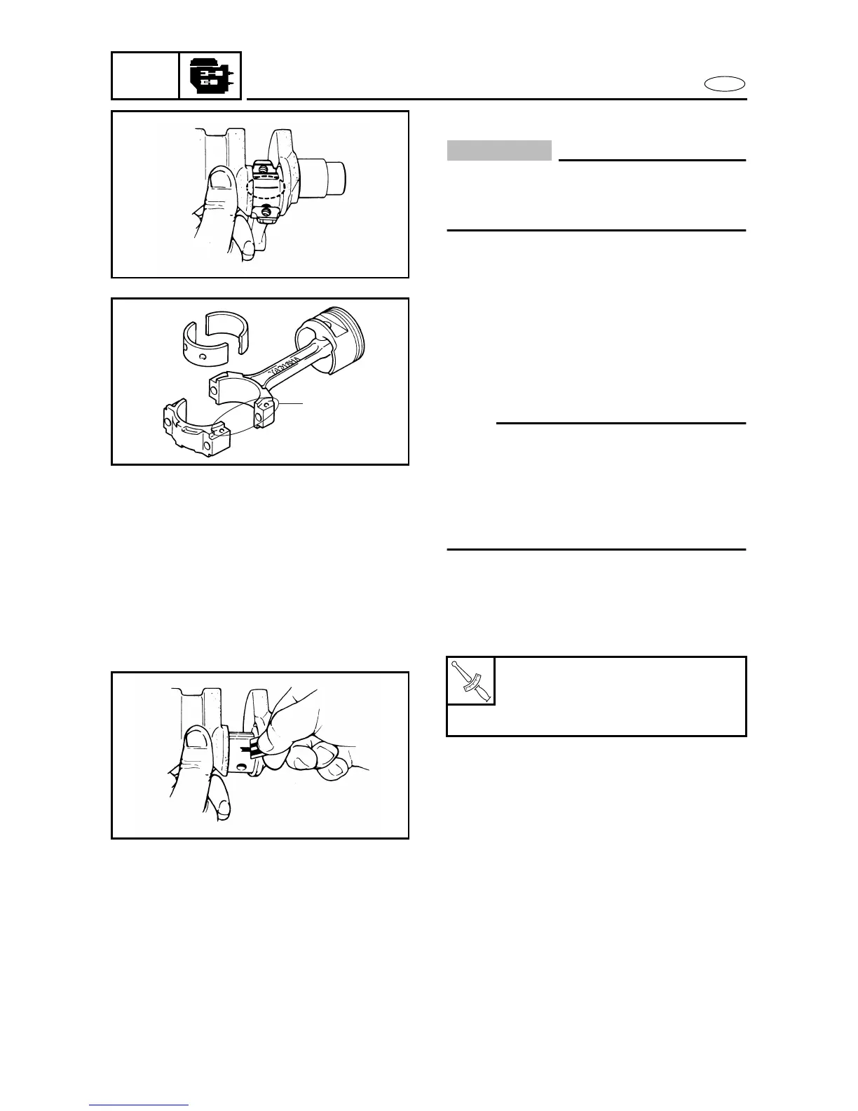
(3) Put a piece of Plastigauge
onto the
crank pin in parallel to the crankshaft.
(4) Assemble the connecting rod onto the
crank pin.
NOTE:
• Make sure the projections a and
“YAMAHA” mark on the connecting rod
faces towards the flywheel side.
• Do not move the crankshaft until the big-
end oil clearance measurement has been
completed.
(5) Apply engine oil onto the threads and
seat of the original connecting rod
bolts.
(6) Tighten the original bolts to the speci-
fied torque in two stages.
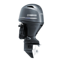
(7) Remove the connecting rod cap.
(8) Measure the width of the compressed
Plastigauge
on each crank pin.
T
R
.
.
Bolt
1st: 15 Nm
(1.5 m • kgf, 11 ft • lb)
2nd: 60˚
5580
a
5590
5600