16.2 List of Parameters
16.2.2 List of Parameters
16-30
*1. The following parameters are automatically set when the INDEXER Module is mounted to the SERVOPACK.
Do not change the setting.
• Pn002 = n.0
• Pn207 = n.1
• Pn50A = 8881h
• Pn50B = 8888h
• Pn510 = 0000h
*2. This parameter is automatically set to 0 if a single-turn absolute encoder is used and Pn002 is set to n.0.
*3. Set a percentage of the motor rated torque.
*4. When the INDEXER Module is mounted to the SERVOPACK, Pn50E is set to 0000h or 3000h according to the
setting of PnB51. Do not change the setting.
*5. When the INDEXER Module is mounted to the SERVOPACK, Pn50F is set to 0000h or 1200h according to the
setting of PnB51. Do not change the setting.
*6. When the INDEXER Module is mounted to the SERVOPACK, this parameter is automatically set according to
the settings of PnB11 and PnB12. (Pn511 = n.8
8, where = 4, 8, or D and
= 6, 8, or F) Do not change
the setting.
*7. When the INDEXER Module is mounted to the SERVOPACK, this parameter is automatically set according to
the settings of PnB1C, PnB1D, PnB1E, and PnB51. (Pn512 = n.0, where = 0 or 1) Do not change the
setting.
*8. When the INDEXER Module is mounted to the SERVOPACK, Pn517 is set to 0000h or 0321h according to the
setting of PnB51. Do not change the setting.
*9. When the INDEXER Module is mounted to the SERVOPACK, this parameter is automatically set to between 0
and 99,999 according to the setting of PnB2D. Do not change the setting.
*10.Normally set this parameter to 0. If you use an External Regenerative Resistor, set the capacity (W) of the Exter-
nal Regenerative Resistor.
*11.The upper limit is the maximum output capacity (W) of the SERVOPACK.
*12.These parameters are for SERVOPACKs with the Dynamic Brake Hardware Option. Refer to the following man-
ual for details.
Σ-7-Series AC Servo Drive Σ-7S/Σ-7W SERVOPACK with Dynamic Brake Hardware Option Specifications Prod-
uct Manual (Manual No.: SIEP S800001 73)
*13.The SGLFW2 is the only Yaskawa Linear Servomotor that supports this function.
*14.Enabled only when Pn61A is set to n.2 or n.3.
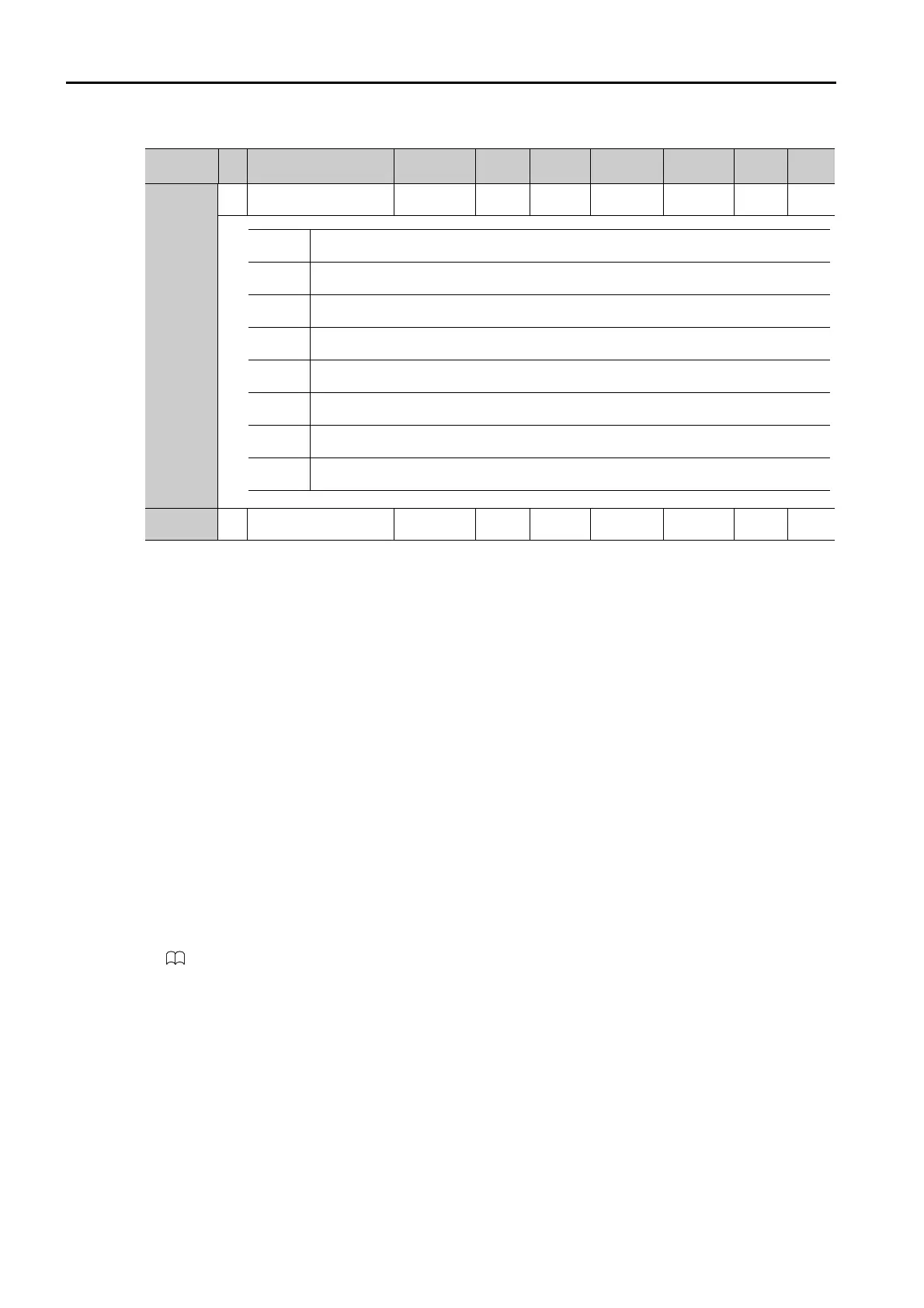
PnB53
2
Input Signal Monitor IN1
Polarity Selection
0000h to
00FFh
–
0050h All
After
restart
Setup
–
PnB54
2
Speed/Position Expan-
sion Function Selection
0, 1
–
0All
After
restart
Setup
–
Continued from previous page.
Parameter
No.
Size
Name
Setting
Range
Setting
Unit
Default
Setting
Applicable
Motors
When
Enabled
Classi-
fication
Refer-
ence
Bit 0
Input Signal Monitor IN1 Bit 0 (/SVON)
(0: Do not invert the data (default setting), 1: Invert the data.)
Bit 1
Input Signal Monitor IN1 Bit 1 (/ALM-RST)
(0: Do not invert the data (default setting), 1: Invert the data.)
Bit 2
Input Signal Monitor IN1 Bit 2 (/P-OT)
(0: Do not invert the data (default setting), 1: Invert the data.)
Bit 3
Input Signal Monitor IN1 Bit 3 (/N-OT)
(0: Do not invert the data (default setting), 1: Invert the data.)
Bit 4
Input Signal Monitor IN1 Bit 4 (/DEC)
(0: Do not invert the data, 1: Invert the data (default setting).)
Bit 5
Input Signal Monitor IN1 Bit 5 (not used)
(0: Do not invert the data (default setting), 1: Invert the data.)
Bit 6
Input Signal Monitor IN1 Bit 6 (/RGRT)
(0: Do not invert the data, 1: Invert the data (default setting).)
Bit 7
Input Signal Monitor IN1 Bit 7 (not used)
(0: Do not invert the data (default setting), 1: Invert the data.)

 Loading...


