3
Module Specifications
3.4.2
Counter Functions and Settings of LIO-01/LIO-02 Modules
3-32
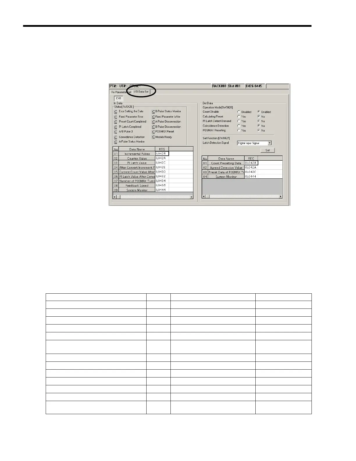
( 3 ) I/O Data Settings
[ a ] Opening the I/O Data Setting Tag Page
Set the I/O data in the I/O Data Tab Page in the Counter Module Window.
Fig. 3.2 I/O Data Tab Page in Counter Module Window
The channel number is fixed to CH1.
The details on the status and I/O data that can be monitored in the I/O Data Tab Page are described
below.
[ b ] In (Input) Data Details
Status Details
The status of each bit of the register is indicated:
●
: ON,
○
: OFF. In offline, this area is displayed
in gray.
Name Bit No. Meaning Remarks
Error Setting the Data 0
1 (ON): Data setting error −
Fixed Parameter Error 1
1 (ON): Fixed parameter setting error −
Preset Count Completed 2
1 (ON): Count value preset completed −
PI Latch Completed 3
1 (ON): PI latch completed −
A/B Pulse 0 4
1 (ON): Feedback pulse is ±1 or less −
Coincidence Detection 5
1 (ON): Coincidence detection ON (in
pulse units)
Detected in pulse units.
A-Pulse Status Monitor 6
1 (ON): High −
B-Pulse Status Monitor 7
1 (ON): High −
Fixed Parameter Write 9
1 (ON): Writing parameter online ON only during write.
A-Pulse Disconnection A
1 (ON): Phase A disconnected −
B-Pulse Disconnection B
1 (ON): Phase B disconnected −
POSMAX Preset C
1 (ON): Completed −
Module Ready
F
1 (ON): Counter processing being
executed
−

 Loading...


