3.2
Basic Module
3-7
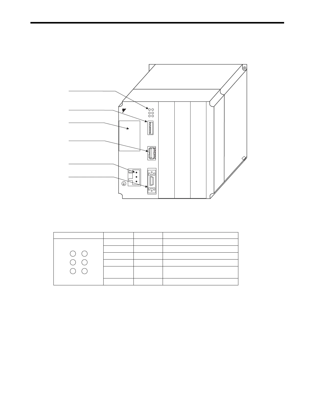
3.2.2 External Appearance, LED Indicators, and Switch Settings
( 1 ) External Appearance
( 2 ) Indicators
The following table shows the indicators that show the operating status of the Basic Module and error
information.
For details on indicator meanings, refer to 12.3.3 ( 2 ) LED Indicator Meanings on page 12-7.
LED indicators
Battery holder
MP2300
YASKAWA
RDY
ALM
TX
RUN
ERR
BAT
BATTERY
SW1
OFFޓޓޓON
M-I/II
CPUޓI/O
POWER
DC24V
DC 0V
STOP
SUP
INIT
CNFG
MON
TEST
Switch
MECHATROLINK
connector
Power supply connector
I/O connector
Option
Option
Option
Indicator Color Status
RDY
Green
Lit during normal operation.
RUN
Green
Lit during execution of user program.
ALM
Red
Lit/blinking when warning occurs.
ERR
Red
Lit/blinking when malfunction occurs.
TX
Green
Lit during transmission of
MECHATROLINK I/II data.
BAT
Red
Lit during battery alarm.
RDY
ERR
TRX
RUN
ALM
BAT

 Loading...


