5.4
Self-configuration
5-29
Slaves detection is performed for each communication in the following order: SERVOPACK,
I/O, inverter.
No connection is detected for stations with disconnected cables, for which a communication
error has occurred, from which no response is received, or with the same station number as
another station.
* Refer to 2.3 System Startup Using Self-Configuration on page 2-59 and 2.1.4 MP2300 Self-
configuration on page 2-5 for information on station data settings, fixed parameters settings,
setting parameter settings, and saving SERVOPACK parameters.
5.4.2 Execution Procedure for Self-configuration Using the DIP Switch
Self-configuration can be executed from the Basic Module DIP switch.
( 1 ) Executing Self-configuration for the First Time after Connecting Devices
Turn ON the power to the MP2300 and then use the procedure described below. With this operation,
self-configuration will be executed for all modules and all new definition files will be created. In
addition, ladder drawings, functions, and all registers will be cleared.
In the following procedure, it is assumed that the power supply to all
Σ-III SERVOPACKs are
already turned ON.
1. Turn OFF the power supply.
Turn OFF the 24-VDC power supply to the MP2300.
2.
Set the DIP switch.
Set the switches INIT and CNFG of the DIP switch SW1 on the MP2300
Basic Module to ON.
3.
Turn ON the power supply.
Turn ON the 24-VDC power supply to the MP2300.
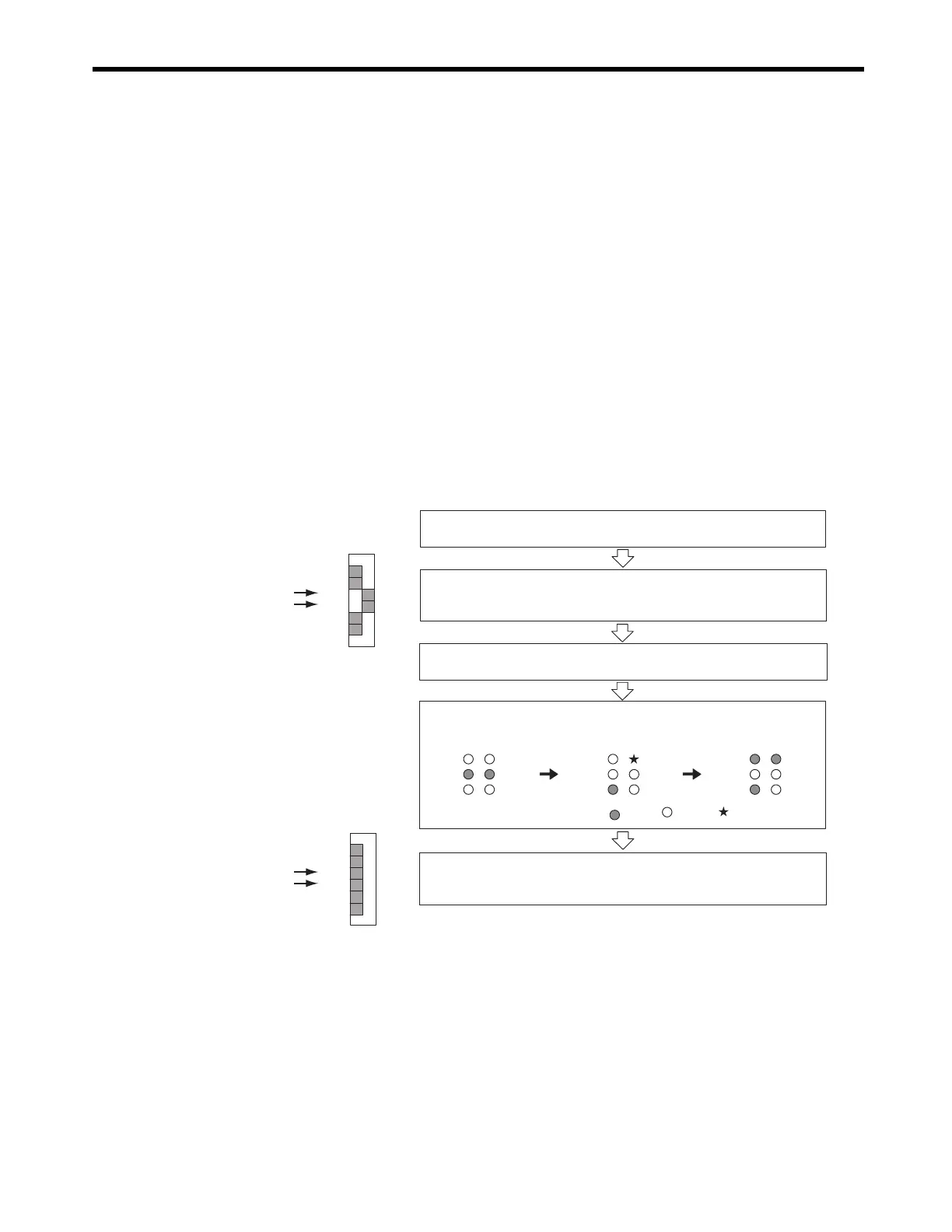
4. Check the LED indicators.
Check that the LED indicators on the MP2300 Basic Module change as
follows.
RDY
ALM
TX BAT
RUN
ERR
RDY
ALM
TX BAT
RUN
ERR
RDY
ALM
TX BAT
RUN
ERR
5. Reset the DIP siwtch.
Set the switches INIT and CNFG of the DIP switch SW1 on the MP2300
Basic Module to OFF.
SW1
OFF
STOP
SUP
INIT
CNFG
MON
TEST
ON
SW1
OFF
STOP
SUP
INIT
CNFG
MON
TEST
ON
: Lit
: Blinking
: Unlit

 Loading...


