5.1
Startup Sequence and Basic Operation
5-3
5.1.2 Startup Sequence
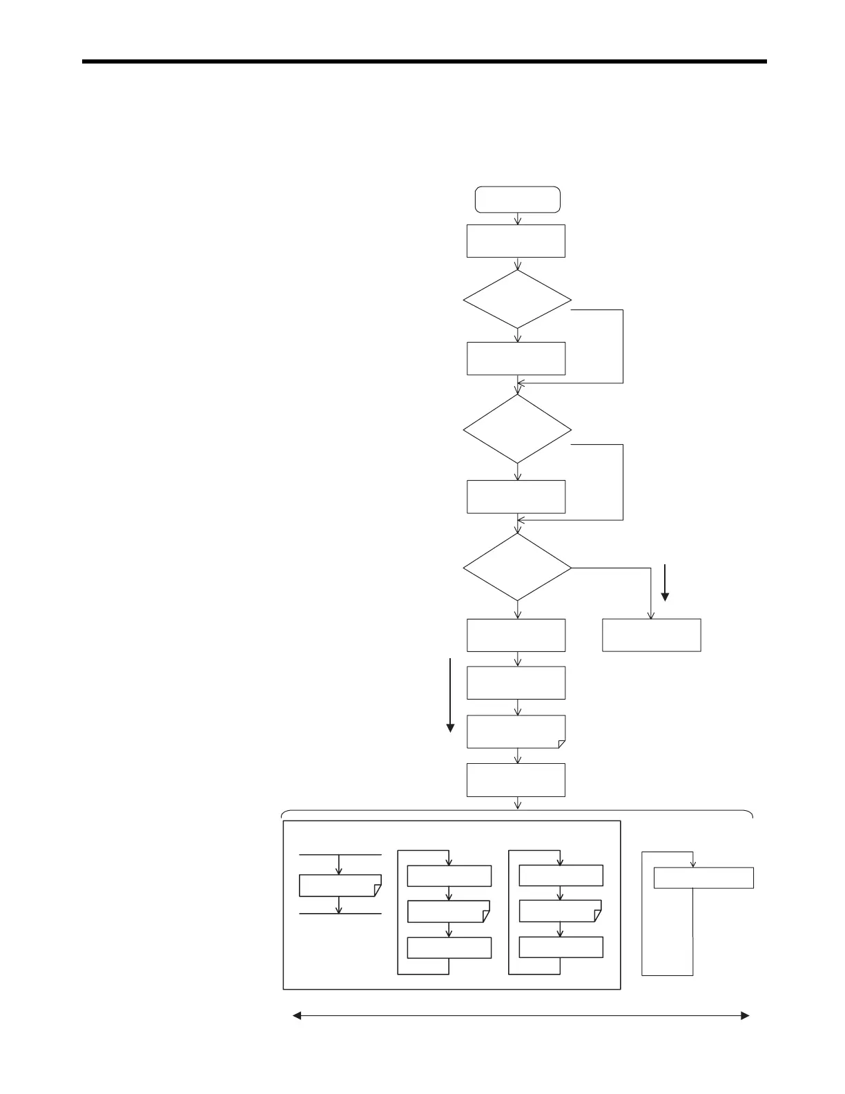
The startup sequence for the MP2300 from the moment when the power has been turned ON
is shown in the following flowchart.
* Refer to 5.1.3 Startup Sequence Operation Details on the next page for details on (1) to (5).
FLASH
ON
OFF
DWG.L
executed
Output
Output
DWG.H
executed
Completed
after one cycle.
DWG.I
executed
Input
Input
Low-speed
scan
High-speed
scan
Interrupt
signal
Ladder program
Power ON
Startup self-
diagnostics (1)
Memory clear
FLASH → RAM
Copy
Watchdog timer
start
DWG.A executed
(Ladder program)
Order of priority
High Low
Online self-diagnostics
(5)
Background
Normal operation
Self-configuration
execution (2)
Configuration mode
S2 indicator (RUN) lit
User program stops
Operation starts (3)
Operation stops (4)
S2 indicator (RDY) lit
Judges the setting
of switch 3 (CNFG)
of DIP switch SW1
Judges the
setting of switch 6 (STOP)
of DIP switch SW1
Judges the
setting of switch 4 (INIT)
of DIP switch SW1

 Loading...


