6
Motion Parameters
6.4.3
Motion Monitoring Parameter Details
6-46
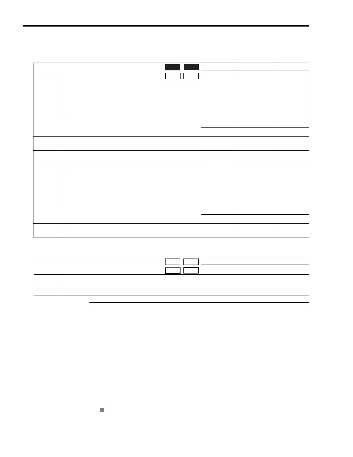
( 32 ) Absolute Infinite Length Axis Position Control Information
( 33 ) Transparent Command Mode
Terminology: Store
The use of “store” here refers to information that is automatically transferred by the CPU system without
any action by the user. This term is mainly used with this meaning in describing motion monitoring param-
eters.
6.4.3 Motion Monitoring Parameter Details
The motion monitoring parameter details are listed in the following table.
Refer to 6.3.3 Monitoring Parameter List on page 6-13 for a list of motion monitoring parameters.
Register number IW
00 indicates the leading input register number + 00. Other register num-
bers listed below indicate input register numbers in the same way.
Refer to 6.1.1 Motion Parameter Register Numbers for MP2300 on page 6-2 for information on
how to find the leading input number.
in the following tables indicates that the item is also compatible with SVR.
OL
5E
Absolute Position at Power OFF (Lower 2 words)
Setting Range Setting Unit Default Value
−
2
31
to 2
31
−
1
pulse 0
Description
This is the information for infinite length axis position control when an absolute encoder is used.
The encoder position is stored in 4 words.
If the Infinite Length Axis Position Information LOAD bit is set to 1 in the RUN Commands (setting parameter
OW
00, bit 7), the position information will be recalculated with the values set here and the Modularized Position at
Power OFF (OL
62 and OL
64).
Refer to 9.4 Absolute Position Detection for Infinite Length Axes on page 9-13 for details.
OL
60
Absolute Position at Power OFF (Upper 2 words)
Setting Range Setting Unit Default Value
−
2
31
to 2
31
−
1
pulse 0
Description
Same as for OL
5E.
Refer to 9.4 Absolute Position Detection for Infinite Length Axes on page 9-13 for details.
OL
62
Modularized Position at Power OFF (Lower 2 words)
Setting Range Setting Unit Default Value
−
2
31
to 2
31
−
1
pulse 0
Description
This is the information for infinite length axis position control when an absolute encoder is used.
The axis position in pulses managed internally by the controller is stored in 4 words.
If the Infinite Length Axis Position Information LOAD bit is set to 1 in the Run Commands (setting parameter
OW
00, bit 7), the position information will be recalculated with the values set here and the Absolute Position at
Power OFF (OL
5E and OL
60).
Refer to 9.4 Absolute Position Detection for Infinite Length Axes on page 9-13 for details.
OL
64
Modularized Position at Power OFF (Upper 2 words)
Setting Range Setting Unit Default Value
−
2
31
to 2
31
−
1
pulse 0
Description
Same as for OL
62.
Refer to 9.4 Absolute Position Detection for Infinite Length Axes on page 9-13 for details.
OW
70 to OW
7E
Command Buffer for Transparent Command Mode
Setting Range Setting Unit Default Value
--
0
Description
This area is used for response data when MECHATROLINK Servo commands are specified directly.
• MECHATROLINK-I and MECHATROLINK-II, 17-byte Mode: Data area = OW
70 to OW
77
• MECHATROLINK- II, 32-byte Mode: Data area = OW
70 to OW
7E
Position
Phase
Speed
Torque
Position
Phase
Speed
Torque
R

 Loading...


