6
Motion Parameters
6.4.2
Setting Parameter List
6-24
6.4.2 Setting Parameter List
The following tables provide details of motion setting parameters.
Refer to 6.3.2 Setting Parameter List on page 6-8 for a list of the motion setting parameters.
Register number OW
00 indicates the leading output register number + 00.Other register num-
bers listed below indicate output register numbers in the same way.
Refer to
6.1.1 Motion Parameter Register Numbers for MP2300
on page 6-2 for information on how
to find the leading output register number.
in the following tables indicates that the item is also compatible with SVR.
in the following descriptions indicate that parameter is enabled in
position control, phase control, speed control, or torque control.
Similarly, in the following descriptions indicate that parameter is
disabled in position control, phase control, speed control, or torque control.
( 1 ) RUN Commands
R
Position
Phase
Speed
Torque
Speed
Torque
Position
Phase
OW
00
RUN Commands
Setting Range Setting Unit Default Value
--
0000H
Description
Bit 0
Servo ON
Sends a SERVO ON command to the SERVOPACK.
0: Servo OFF (default)
ON: Servo ON
Bit 1
Machine Lock
During the machine lock mode, the Target Position (CPOS) (monitoring parameter IL
10) will be updated
but no movement will occur on the axis.
A change in the machine lock mode is valid after all pulses have been distributed. The machine lock mode
cannot be changed during speed or torque control.
0: Machine lock mode released (default)
1: Machine lock mode
Bit 4
Latch Request
Store the current position when the latch signal turns ON as the Machine Coordinate Latch Position (LPOS)
(monitoring parameter IL
18).
When latch detection is completed, the Latch Completed bit will turn ON in the Position Management Status
(monitoring parameter IW
0C, bit 2).
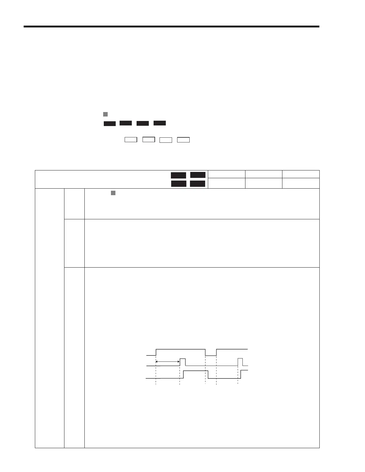
To perform latch detection again, change this bit from 0 to 1.
Set the latch signal to be used in Latch Input Signal Type of Function 2 (setting parameter OW
04, bits 0 to
3).
This function is achieved using the Servo command expansion area and can be executed only with the
MECHATROLINK-II, 32-byte Mode communication method.
Do not change this bit to 1 during execution of the motion commands for zero point return, external positioning,
or latching. Doing so may result in a warning at the SERVOPACK.
0: Latch request OFF (default)
1: Latch request ON
Position
Phase
Speed
Torque
R
∗
T ≥ t
1
+ t
2
+ t
3
OB004
IB0C2
T
∗
t2: Two scans
t1: MECHATROLINK communication cycle
T: Latch processing time
Latch signal
t3: SERVOPACK latch processing preparation time (≤ 4 ms)
Where

 Loading...


