3.5
Communication Modules (Optional)
3-51
3.5 Communication Modules (Optional)
The following Communication Modules can be mounted to the MP2300: the 218IF-01, the 217IF-01,
the 260IF-01, and the 261IF-01 Modules.
3.5.1 218IF-01 Module
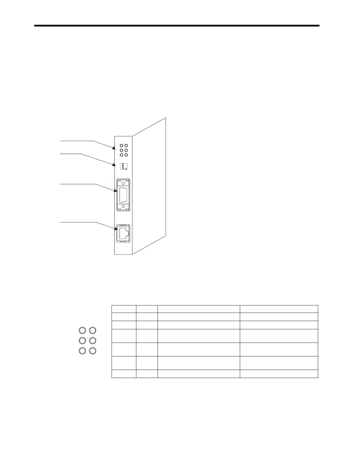
( 1 ) External Appearance and Outline of Functions
( 2 ) LED Indicators and Switch Settings
[ a ] LED Indicators
The following table shows the 218IF-01 Module status when each LED indicator is lit or unlit.
Ethernet connector
10Base-T
LED indicators
Serial connector
(RS-232C)
Switch
218IF-01
ERR
COL
RX
RUN
STRX
TX
INIT
TEST
ONOFF
PORT
10Base-T
The 218IF-01 Module has an RS-232C serial interface and an
Ethernet interface mounted in it. Personal computers, HMI
devices, and controllers manufactured by other companies can
be connected to the 218IF-01 Module via the PORT or
10Base-T connectors.
For details, refer to the MP2300 Machine Controller
Communication Module User’s Manual (Manual No.
SIEPC8807004
).
Indicator Color Status When Lit Status When Unlit
RUN Green Normal operation Error occurrence
ERR Red Malfunction (lights/blinks) Normal operation
STRX Green
Transmitting or receiving RS-232C
data
No data being transmitted or received
COL Red
Ethernet collision status
: Collision
Ethernet collision status
: No collision
TX Green
Transmitting Ethernet transmission sta-
tus
No data being transmitted
RX Green Receiving Ethernet receiving status No data being received
ERR
COL
RX
RUN
STRX
TX

 Loading...


