4.5
Communication Module (Optional) Connections
4-71
4.5.4 261IF-01 Module
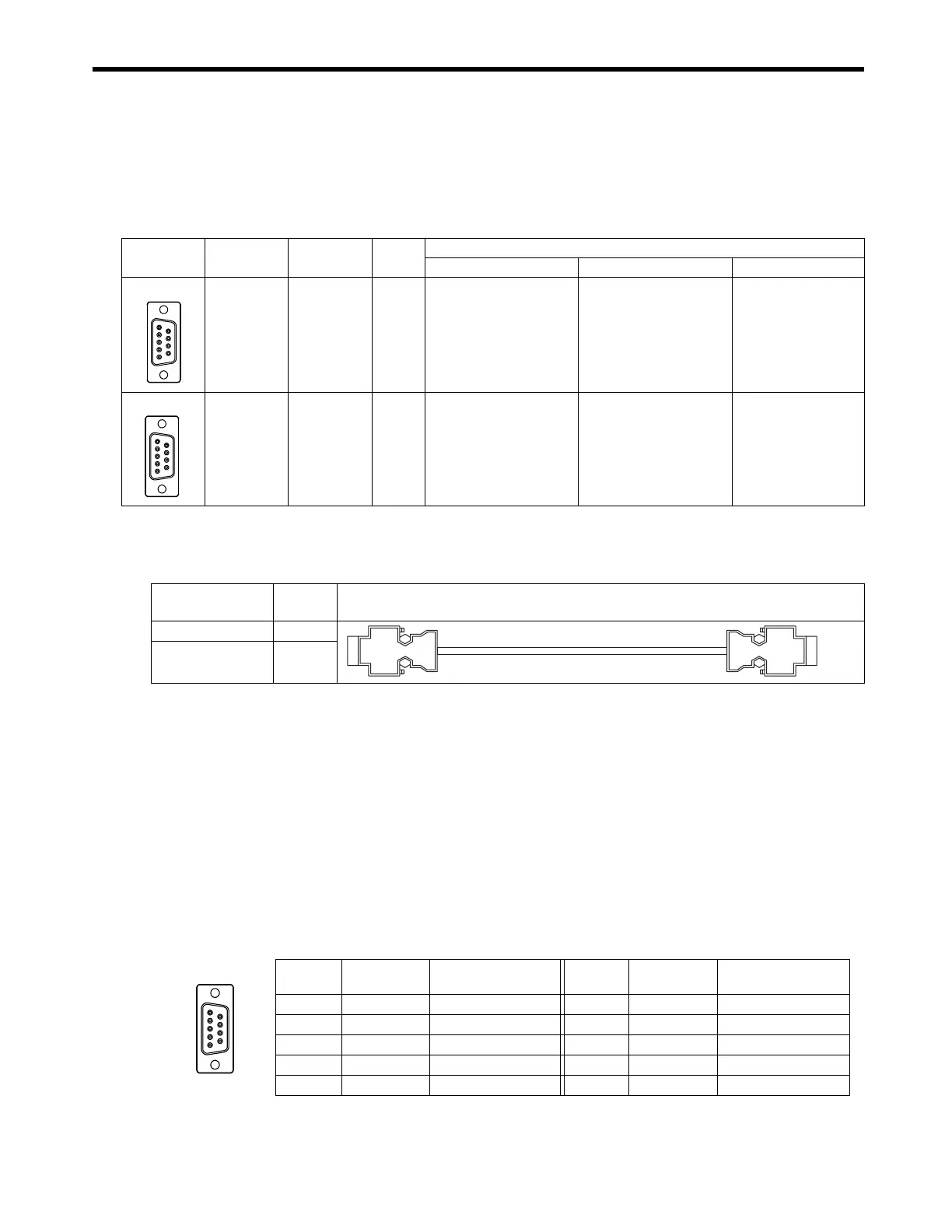
( 1 ) Connectors
The following diagram shows 261IF-01 Module connectors.
( 2 ) Cables
■
RS-232C Cable
■
PROFIBUS Cable
The standard cables for PROFIBUS are not available. Assemble a cable using commercially avail-
able connectors with the specifications described in (1) and cable. Access to PROFIBUS organiza-
tion home page for the PROFIBUS product list. When selecting connectors, check the position and
direction of the cable outlet so that the PROFIBUS connector connection and the RS232-C connector
connection are not interfered each other.
( 3 ) Connector Pin Arrangement
[ a ] PORT Connector
The PORT connectors is used to connect the MP2300 to computers and HMI devices via an RS-232C
connection.
Connector Name
Connector
Name
No. of
Pins
Connector Model
Module Cable Manufacturer
RS-232C PORT 9
17LE-13090-27(D2BC)
9-pin D-sub
female connector
17JE-23090-02
(
D8B
)
9-pin D-sub
male connector
DDK Ltd.
PROFIBUS PROFIBUS 9
17LE-13090-27(D33C)
9-pin D-sub
female
connector
−
DDK Ltd.
PORT
PROFIBUS
Model Number Length
Appearance
(JEPMC-W5311-
)
JEPMC-W5311-03 2.5 m
JEPMC-W5311-15 15 m
Pin
Number
Signal Name Description
Pin
Number
Signal Name Description
1FGFrame ground 6 −−
2SDSend data 7SGSignal ground (0V)
3RDReceive data 8 −−
4RSReady to send 9ERData terminal ready
5CSClear to send
1
69
5

 Loading...


