9.4
Absolute Position Detection for Infinite Length Axes
9-19
9.4.3 Setting the Zero Point and Turning ON Power as Simple Absolute Positions
( 1 ) Calculating the Zero Point of the Machine Coordinate System
If using the simple absolute infinite length position control, the MP2300 calculates the axis position
(i.e., current position for the machine coordinate system) as follows when the power is turned ON.
Current position for the machine coordinate system (monitoring parameter IL
10
*1
or
IL
16
*1
) = Encoder position when servo power is turned ON
*2
+ Zero Point Offset (setting
parameter OL
48)
To assign the current position of the machine coordinate system as the zero position, set the
OL
48 (encoder position when servo power turns ON) to a negative value. In other words, set
OL
48 to the difference between OL
48 and IL
10 (or IL
16).
* 1. Use the IL
10 to make the machine coordinate reference position a positive value, and
IL
16 to make a negative value.
* 2. The encoder position when the servo power is turned ON is calculated with the following equation:
Multiturn data
×
Number of encoder pulses + initial increment pulses. Refer to your
SERVOPACK manual for information on the initial increment pulses.
Example: IL
10 = 10,000 and OL
48 = 100
Set the encoder position when servo power is turned ON to a negative value as shown below.
OL
48
-
IL
10 = 100
-
10000
=
-
9900
Set OL
48 to -9900 to assign the current position in the machine coordinate system as the zero
point.
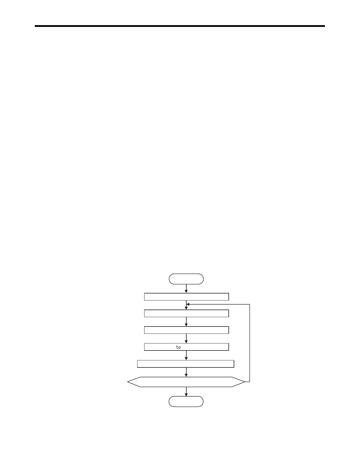
( 2 ) Setting the Zero Point for Simple Absolute Infinite Axis Position Control
The procedure to set the zero point for a simple absolute infinite axis position control is shown
below.
Repeat for every axis.
Start
End
YES
NO
Servo ON
JOG to move close to the zero point.
JSTEP to move to the zero point.
Set OL48 OL48 - IL10.
Use the ZSET command to set the zero point.
Has the setting for the required axis been completed?

 Loading...


