2
System Startup and Sample Programs
2.2.3
Operation Check 3: Phase Control - Electronic Shaft
2-48
2.2.3 Operation Check 3: Phase Control - Electronic Shaft
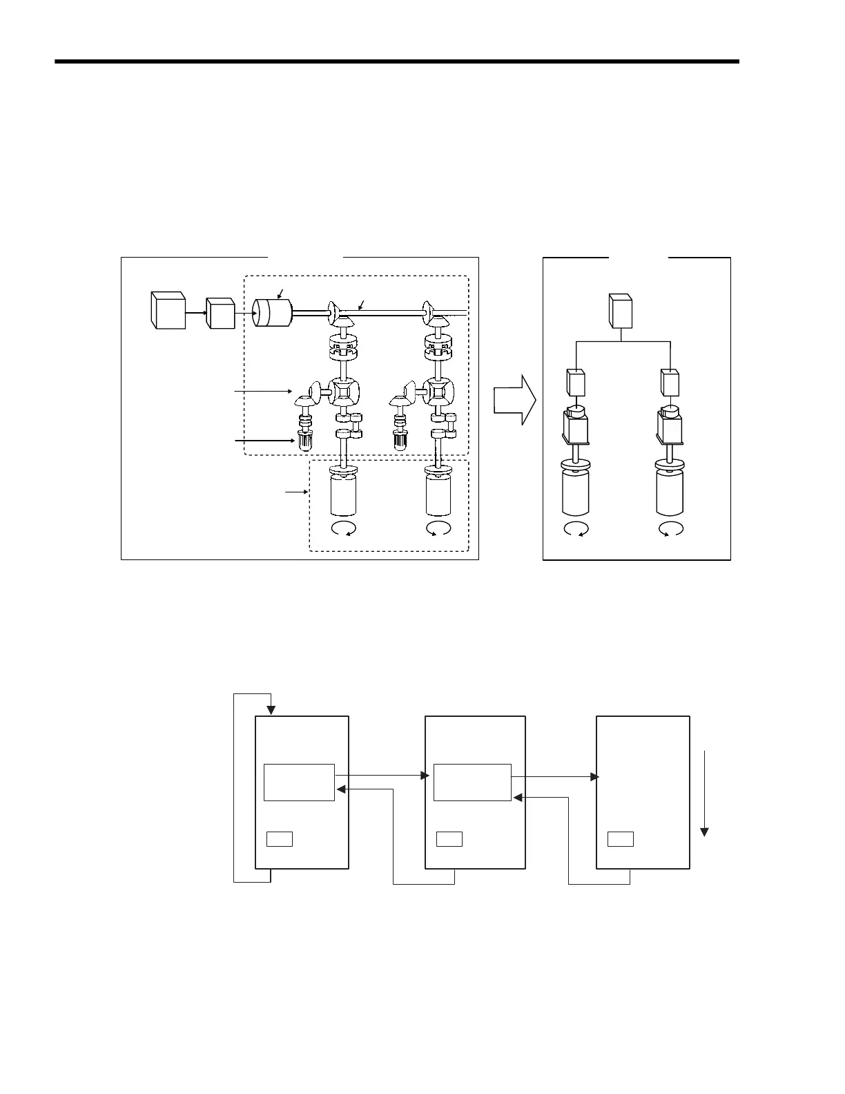
( 1 ) Machine Outline
As shown in the following figure, the Servomotor performs the same operation as rolls No. 1 and No.
2 connected to the line shaft. No phase matching, however, is used.
( 2 ) Program Overview
Use the ladder program (H06.01 Drawing) to check the above operation. The two axes synchronize
to a virtual master axis according to the entered speed settings, and axis 1 and axis 2 rotate in exactly
the same way.
Refer to 2.2.3 ( 5 ) Sample Program Details on page 2-50 for details of H06.01 Drawing.
A simple device is used in this example to describe the MP2300 system startup.
This device has no power OFF circuit for the SERVOPACK in the event of emergency stops or
overtravel. Include a proper emergency stop circuit in actual devices.
MP2300
Servo-
motor
SERVO-
PACK
No. 1
Controller
Driver
Phase matcher
Motor
Gear
Differential gear
Clutch
Operating
section
Line shaft
Line shaft drive motor
No. 2
RollRoll
New Type
Existing Type
Name H06
END
SEE
Name H06.01
END
SEE
END
Parent Drawing
H Drawing H06.01 Drawing
High-speed scan
Grandchild DrawingsChild Drawings
H06 Drawing
Position control
Electronic shaft
• Axis 1
• Axis 2

 Loading...


