3
Module Specifications
3.5.4
261IF-01 Module
3-60
DeviceNet Communication Specifications
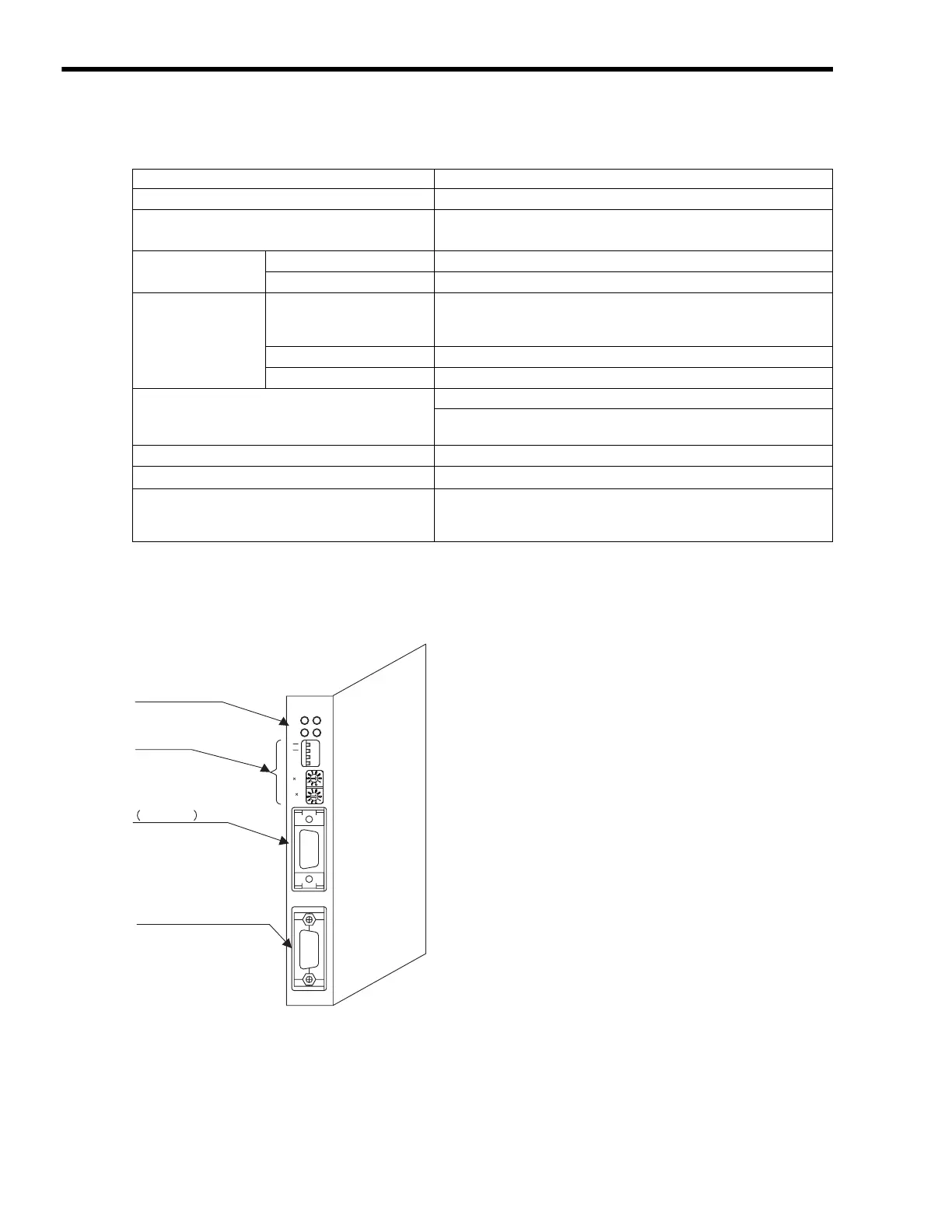
3.5.4 261IF-01 Module
( 1 )
External Appearance and Outline of
Functions
Item Specifications
Number of Lines
1
Supported Communication Methods
• I/O communication functions (Polled, Bit Strobed)
• Explicit messages (Support only for master function)
I/O Communication
Max. Number of Slaves
63
Max. Number of I/O Bytes
2,048 bytes, 256 bytes/node for max. number of I/O bytes.
Message
Communication
(Only for Masters)
Max. Number of Nodes for
Message
Communication
63 nodes
Max. number of nodes for simultaneous communication: 8
Max. Message Length
256 bytes
Function for Execution
MSG-SND function
Settings
2 rotary switches on front panel: Node address
DIP switch on front panel: Band rate
Master/Slave mode
Indicators
2 LEDs: MS, NS
Power Supply Voltage for Communication
24 VDC
±
10% (supplied by special cable)
Current Consumption
Communication power supply: 45 mA max. (supplied from
communication connector).
Internal circuit power supply (supplied from Basic Module).
The 261IF-01 Module has an RS-232C serial interface and a
PROFIBUS interface mounted in it. Personal computers, HMI
devices, and controllers manufactured by other companies can
be connected to the 261IF-01 Module via the PORT or
PROFIBUS connectors.
For details, refer to the MP2300 Machine Controller
Communication Module User’s Manual (Manual No.
SIEPC8807004
).
PROFIBUS connector
LED indicators
Serial connector
RS-232C
Switches
ERR
TRXSTRX
RUN
261IF-01
TEST
INIT
ONOFF
10
1
PORT
PROFIBUS

 Loading...


