3.5
Communication Modules (Optional)
3-61
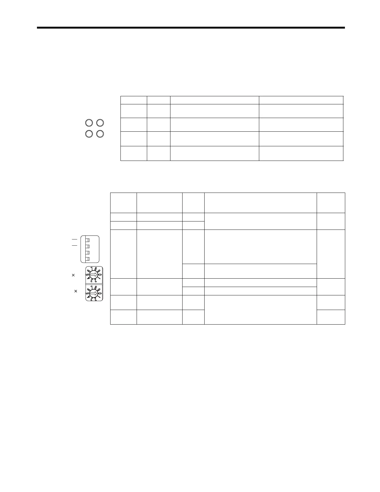
( 2 ) LED Indicators and Switch Settings
[ a ] Indicators
The following table shows the 261IF-01 Module status when each LED indicator is lit or unlit.
[ b ] Switch Settings
The following table shows the 261IF-01 Module switch settings.
Indicator Color Status When Lit Status When Unlit
RUN Green
Normal operation Error occurrence
ERR Red
Malfunction (lights/blinks) Normal operation
STRX Green
Transmitting or receiving RS-232C
(PORT) data
No data being transmitted or received
TRX Green
Transmitting or receiving PROFIBUS
data
No data being transmitted or received
ERR
TRXSTRX
RUN
Switch Name
Status/
Setting
Range
Function
Factory
Setting
− Reserved
−
Always leave set to OFF. OFF
− Reserved
−
INIT
Initial Startup
ON
For engineering communications. Starts the serial
communication using the default parameters
except setting of automatic reception functions.
Given higher priority than the Basic Module Flash
Startup and Self-configuration Startup.
OFF
OFF
Set to OFF for Basic Module Flash Startup and
Self-configuration Startup.
TEST
TEST
ON
System use
OFF
OFF
Normal operation. (Always leave turned OFF.)
×
10
Node Address 10s
Digit Setting
0 to 6
Sets the node address in the range from 1 to 64.
(Rotary decimal switch).
0
×
1
Node Address
1s Digit Setting
0 to 9
1
TEST
INIT
ONOFF
10
1

 Loading...


