4.4
I/O Module (Optional) Connections
4-31
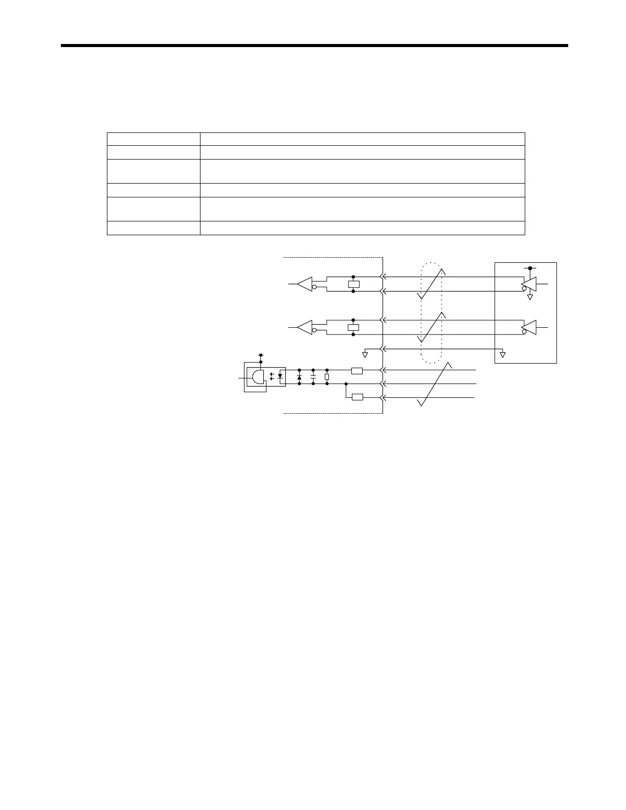
( 7 ) Pulse Input Circuit
The following table shows the LIO-01/LIO-02 Module pulse input circuit specifications.
Fig. 4.8 Pulse Input Circuit
Item Specifications
Number of Circuits
1 (Phase-A/B/Z input)
Input Circuit
Phase-AB: 5-V differential input, not isolated, max. frequency: 4 MHz
Phase-Z: 5-V/12-V photocoupler input, max. frequency: 500 kHz
Input Mode
Phase-A/B, signed, incremental/decremental
Latch Input
Pulse latch on phase-Z or DI_01.
Response time: 5
µ
s max. for phase-Z input; 60
µ
s max. for DI_01 input.
Other Functions
Coincidence detection, counter preset and clear
+5 V
0 V
Phase-A
A1
220Ω
Pulse Generator
Phase-B
PA
PAL
PB
PBL
GND
B1
A2
B2
B3
B4
A4
A3
+5 V
Latch input or
phase-Z pulse
PC
PCL5
PCL12
R
R
R
220Ω
R

 Loading...


