4.4
I/O Module (Optional) Connections
4-33
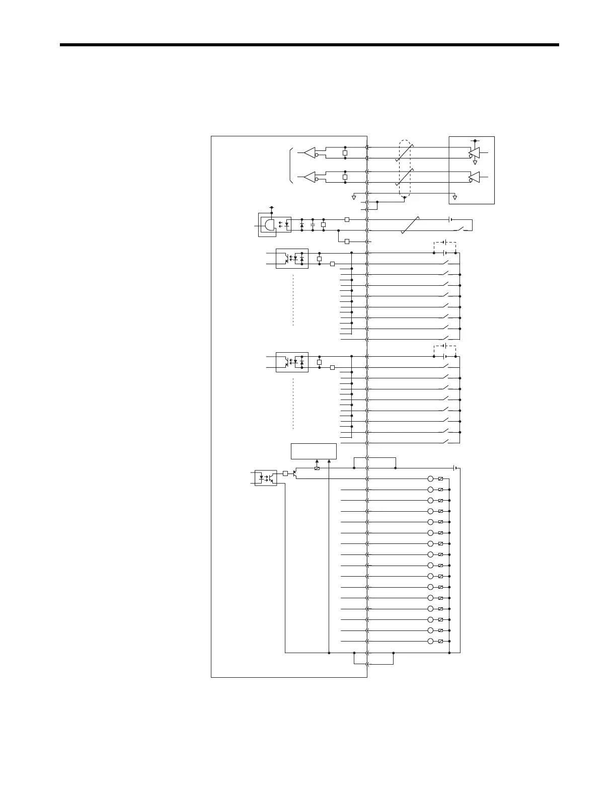
( 9 ) LIO-02 Module Connections
The following diagram shows a connection example for LIO-02 Module connectors.
Connect a fuse suitable for the load specifications in the output signal circuit in series with the
load. If an external fuse is not connected, load shorts or overloads could result in fire, destruction
of the load device, or damage to the output element.
The pins No. A5 and B5, and the pins No. A6 and B6 are internally connected. Connect them
externally as well.
220Ω
220Ω
+5V
0V
Phase-A
Pulse generator
+5V
Pulse input
Latch input
or phase-Z
pulse
Latch input o
phase-Z puls
Phase-B
5V
A2
B2
A4
PB
PBL
GND
PC
PCL5
PCL12
A3
A24
B24
B3
B4
PA
PAL
A1
B1
External input
signals
DI_COM0
DI_01
DI_02
DI_03
DI_04
DI_05
DI_06
DI_07
DI_00
A23
B22
A22
B21
A21
B20
A20
B19
A19
24 VDC
Digital input
R
R
External input
signals
DI_COM1
DI_09
DI_10
DI_11
DI_12
DI_13
DI_14
DI_15
DI_08
B23
B18
A18
B17
A17
B16
A16
B15
A15
24 VDC
Digital input
R
R
R
R
R
R
R
L
L
L
L
L
L
L
Digital output
External output
signals
L
L
L
L
L
L
L
L
L
Fuse blowout
detection circuit
Fuse
24 VDC
Fuse
DO_24V
DO_24V
DO_15
DO_14
DO_13
DO_12
DO_11
DO_10
DO_09
DO_08
DO_07
DO_06
DO_05
DO_04
DO_03
DO_02
DO_01
DO_00
DO_COM
DO_COM
B6
A6
B14
A14
B13
A13
B12
A12
B11
A11
B10
A10
B9
A9
B8
A8
B7
A7
A5
B5
R

 Loading...


