4
Mounting and Wiring
4.4.2
LIO-04/LIO-05 Module Connections
4-40
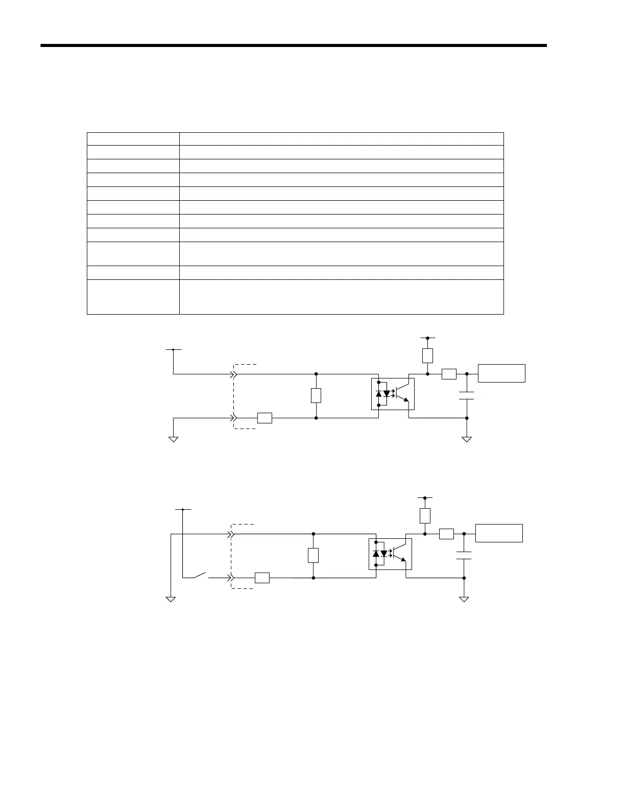
( 6 ) Input Circuit
The following table shows the LIO-04/LIO-05 Module input circuit specifications.
Fig. 4.9 Digital Input Circuit (Sink Mode Input)
Fig. 4.10 Digital Input Circuit (Source Mode Input)
Item Specifications
Inputs
32 points
Input Format
Sink mode/source mode input
Isolation Method
Photocoupler (PS2805-4)
Input Voltage
±
24 VDC (+19.2 to +28.8 V)
Input Current
4.1 mA (typ.)
ON Voltage/Current
15 VDC min./2.0 mA min.
OFF Voltage/Current
5 VDC min./1.0 mA min.
ON Time/OFF Time
ON: 0.5 ms max.
OFF: 0.5 ms max.
Number of Commons
Common ground
Other Functions
DI_00 is shared with an interrupt input. If DI_00 is turned ON while interrupts are
enabled, the interrupt processing drawing is executed.
DI_01, DI_16, and DI_7 are the same as DI_00.
5.6kΩ/ 0.5W
Vcc
DICOM
+24V
DI_IN
Input register
0
24
Photocoupler
R
R
R
R
5.6k
Ω/ 0.5W
Vcc
DICOM
+24V
DI_IN
Input register
0
24
R
R
R
R
Photocoupler

 Loading...


